Industrial Radar Level Transmitter
Industrial Radar Level Transmitter: A Practical Engineering Guide to Selection and Application
In the landscape of industrial process control, the demand for non-contact, high-precision measurement has made the industrial radar level transmitter a cornerstone technology. Unlike contact-based methods, radar technology offers a robust solution for monitoring liquids, slurries, and solids under extreme conditions of temperature, pressure, and chemical volatility. As industries move toward greater automation, understanding the nuances of Radar Level Meters becomes essential for ensuring process safety and operational efficiency.
This guide examines the engineering principles, selection criteria, and installation requirements necessary for deploying radar level measurement systems in B2B industrial environments.
1. Core Measurement Principles
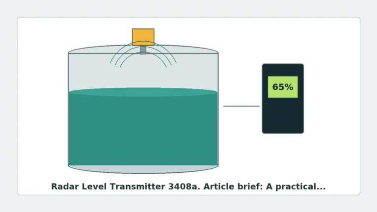
Radar level measurement is based on the "Time of Flight" (ToF) principle. The transmitter emits electromagnetic pulses or a continuous wave toward the medium. These waves reflect off the surface of the material and return to the sensor. By calculating the time elapsed or the frequency shift between emission and reception, the device determines the distance to the product surface.
Pulse Radar (Time of Flight)
Pulse radar transmitters emit a microwave signal in short, periodic bursts. The device measures the time it takes for the pulse to travel to the surface and back. This method is energy-efficient and suitable for many standard liquid applications. However, it may struggle with low-dielectric materials where the reflected signal is weak.
FMCW (Frequency Modulated Continuous Wave)
FMCW technology is increasingly the standard for high-precision industrial radar level transmitters. Instead of pulses, the device emits a continuous signal with a constantly changing frequency. The difference in frequency between the emitted and received signal is proportional to the distance. FMCW offers superior signal-to-noise ratios, making it ideal for measuring materials with low dielectric constants or in vessels with significant internal obstructions.
2. Frequency Bands and Their Industrial Impact
The frequency at which a radar transmitter operates significantly influences its performance, beam angle, and sensitivity. Most industrial units operate in either the C-band (approx. 6 GHz), K-band (approx. 26 GHz), or W-band (approx. 80 GHz).
| Frequency Band | Typical Frequency | Beam Angle | Best Use Case |
| :— | :— | :— | :— |
| C-Band | 6 GHz | Wide (approx. 20-30°) | Applications with heavy foam or steam; large tanks. |
| K-Band | 26 GHz | Medium (approx. 8-12°) | General-purpose liquid and solid measurement in medium-sized vessels. |
| W-Band | 80 GHz | Narrow (approx. 3-4°) | Small vessels, narrow nozzles, and high-precision requirements. |
High-frequency 80 GHz radar has revolutionized the market by providing a very narrow beam. This allows the signal to avoid internal tank structures like agitators, heating coils, and ladders, which previously caused interference for lower-frequency models.
3. Selection Criteria for Industrial Radar Level Transmitters
Choosing the correct industrial radar level transmitter requires a thorough analysis of the process environment. Engineers must prioritize the following factors:
Dielectric Constant (εr)
The dielectric constant of the medium determines how much energy is reflected back to the sensor. Water has a high dielectric constant (εr ≈ 80) and is easy to measure. Hydrocarbons, oils, and certain powders have low dielectric constants (εr < 2), which absorb more of the radar signal. For low-εr materials, FMCW radar or guided wave radar is often required to ensure a reliable signal return.
Process Conditions
* Temperature and Pressure: Radar sensors are generally unaffected by vacuum or high pressure, but the antenna materials (typically PTFE, PFA, or Stainless Steel) must be compatible with the process temperature. High-temperature extensions are available for applications exceeding 200°C (392°F).
* Vapor and Dust: While radar penetrates dust and vapor better than ultrasonic sensors, extremely dense steam or heavy dust can attenuate the signal. In such cases, lower-frequency radar (C-band) or air-purging systems for the antenna may be necessary.
Vessel Geometry
The height and diameter of the tank, along with the presence of internal obstructions, dictate the required beam angle. A narrow beam (high frequency) is essential for tall, narrow silos or tanks with complex internals.
4. Installation Considerations and Best Practices
Even the most advanced industrial radar level transmitter will fail if installed incorrectly. Engineering teams should adhere to the following guidelines to ensure data integrity:
1. Nozzle Height and Diameter: The antenna should ideally extend slightly beyond the bottom of the mounting nozzle to prevent signal ringing and interference within the nozzle itself. If using a long nozzle, a higher-frequency radar with a narrower beam is required.
2. Avoid the Center: Never install the transmitter in the dead center of a domed-roof tank. This can cause multiple reflections that amplify noise. Conversely, do not install it too close to the tank wall (maintain a minimum distance of 200mm to 500mm depending on the beam angle) to avoid side-lobe interference.
3. Obstruction Clearance: Ensure the radar beam's "footprint" at the bottom of the tank does not intersect with agitators, pipes, or inflow streams. If an agitator is present, the software must be configured with a "False Signal Suppression" or "Static Map" to ignore these reflections.
4. Inflow Streams: Position the sensor away from the product inlet. Turbulent surfaces caused by filling can scatter the radar signal, leading to erratic readings.
5. Applications Across Key Industries
Radar technology is versatile, but its implementation varies by sector:
* Water and Wastewater: Used for level monitoring in lift stations, chemical storage (alum, lime), and open channel flow. Radar is preferred over ultrasonic sensors here because it is unaffected by air temperature fluctuations or wind.
* Chemical Processing: Radar is ideal for corrosive acids and bases. Because it is non-contact, the sensor is not degraded by the media, provided the wetted parts (antenna) are chemically resistant.
* Oil and Gas: High-precision Radar Level Meters are used for custody transfer and inventory management in large storage tanks where millimeter-level accuracy is required.
* Food and Beverage: Hygienic radar transmitters with flush-mounted diaphragms are used to monitor ingredients in stainless steel tanks, surviving CIP (Clean-In-Place) cycles and high-pressure washdowns.
6. Limitations and Risks
While highly reliable, radar is not a "one-size-fits-all" solution. Engineers must be aware of specific limitations:
* Heavy Foam: Depending on the density and conductivity, foam can either reflect the signal (measuring the top of the foam), allow the signal to pass (measuring the liquid), or absorb the signal entirely (resulting in signal loss). C-band radar is generally better at penetrating foam than higher frequencies.
* Extreme Turbulence: Rapidly moving surfaces can scatter the signal. While software filtering can smooth the output, extreme cases may require a stilling well or bypass chamber to provide a calm surface for measurement.
* Antenna Buildup: In applications with viscous or crystallizing media, material can build up on the antenna. While many modern radars can compensate for minor coating, heavy buildup will eventually cause a signal loss. Choosing a PTFE-coated drop antenna or using an air-purge connection can mitigate this.
7. Maintenance and Calibration
One of the primary B2B advantages of the industrial radar level transmitter is its low maintenance requirement. Since there are no moving parts and no contact with the media, wear and tear are minimal.
* Verification: Periodic verification can be performed by comparing the radar reading against a manual dip-tape measurement. Many modern units also feature internal diagnostics that monitor signal strength and electronics health.
* Calibration: Most radar units are pre-calibrated at the factory. Field calibration typically involves setting the 4mA (empty) and 20mA (full) points relative to the tank height.
8. Buyer’s Confirmation Checklist
When sourcing an industrial radar level transmitter from an international manufacturer, procurement and engineering teams should confirm the following technical details:
1. Medium Properties: What is the dielectric constant? Is it a liquid or a solid?
2. Process Interface: What is the flange or thread size? Does it require a hygienic connection?
3. Output Protocol: Is 4-20mA HART sufficient, or is Modbus, Profibus, or Foundation Fieldbus required for the control system?
4. Hazardous Area Ratings: Does the site require ATEX, IECEx, or UL explosion-proof certifications?
5. Accuracy Requirements: Is the goal general process control (±3mm to ±5mm) or high-precision inventory tank gauging (±1mm)?
9. Frequently Asked Questions (FAQ)
Q: Can a radar level transmitter measure through a plastic tank wall?
A: Yes. If the tank is made of a non-conductive material like PE, PP, or GRP, the radar signal can pass through the top of the tank, allowing for measurement without a hole in the vessel. This is common in chemical IBCs.
Q: What is the difference between Radar and Ultrasonic sensors?
A: Ultrasonic sensors use sound waves and are affected by air temperature, pressure, and vapors. Radar uses electromagnetic waves, which travel at the speed of light and are largely unaffected by the atmosphere in the tank, making radar more reliable for complex industrial processes.
Q: How does a stilling well help?
A: A stilling well is a vertical pipe installed inside the tank. It protects the radar signal from foam, turbulence, and internal obstructions, effectively turning a complex tank into a simple, narrow pipe measurement.
Q: Is 80 GHz always better than 26 GHz?
A: Not necessarily. While 80 GHz offers a narrower beam and better precision, 26 GHz (or 6 GHz) may be superior in applications with heavy foam or where the antenna is prone to condensation and buildup, as the longer wavelengths are less affected by these factors.
By carefully matching the technology to the specific constraints of the application, engineers can ensure that an industrial radar level transmitter provides years of accurate, maintenance-free service in even the most demanding environments.