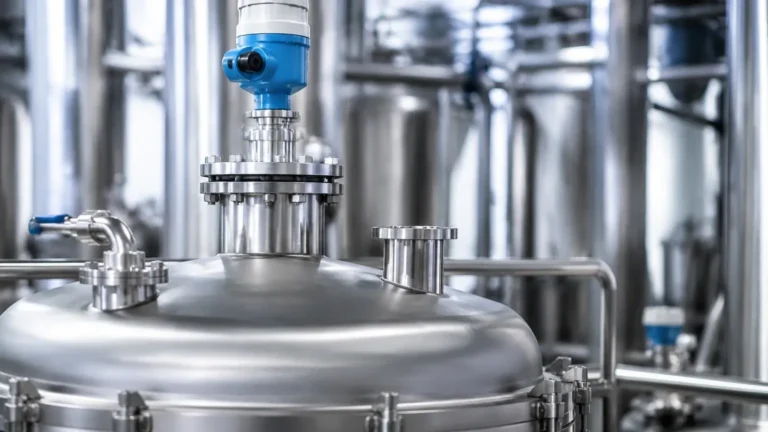
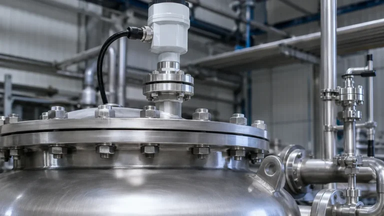
Guided Wave Radar Level Transmitter Honeywell
Guided Wave Radar Level Transmitter Honeywell: A Technical Guide for Industrial Selection
In the landscape of industrial process control, accurate level measurement is critical for safety, efficiency, and inventory management. Guided Wave Radar (GWR) technology has emerged as one of the most versatile and reliable methods for monitoring liquids, slurries, and solids. For engineering professionals evaluating high-end instrumentation, such as the guided wave radar level transmitter Honeywell SmartLine series, understanding the underlying physics and application constraints is essential for successful integration.
This guide explores the engineering principles of GWR, provides practical selection criteria, and outlines the technical considerations necessary for deploying Radar Level Meters in demanding industrial environments.
1. Measurement Principle: Time Domain Reflectometry (TDR)
Guided Wave Radar operates on the principle of Time Domain Reflectometry (TDR). Unlike non-contact radar, which broadcasts electromagnetic pulses through the air, a GWR transmitter directs low-power microwave pulses along a physical conductor (the probe).
The Physics of Reflection
When these pulses reach the surface of the medium being measured, a portion of the energy is reflected back to the transmitter. This reflection is caused by a change in the dielectric constant ($ε_r$) between the upper medium (usually air or gas) and the process medium. The transmitter measures the "time of flight"—the interval between the pulse emission and the reception of the echo—to calculate the distance.
Distance is determined by the formula:
Distance = (Speed of Light × Time of Flight) / 2
Because the pulses are guided by a probe, the signal is less susceptible to attenuation caused by foam, steam, or turbulence, which can often dissipate the signal of non-contact radar systems.
2. Key Components and Probe Selection
The performance of a guided wave radar level transmitter depends heavily on the probe geometry. Selecting the correct probe type is the most critical step in the engineering phase.
Probe Types and Characteristics
| Probe Type | Best For | Advantages | Limitations |
| :— | :— | :— | :— |
| Single Rod/Cable | High viscosity liquids, slurries, and solids. | Easy to clean, resistant to coating/clogging. | Sensitive to internal tank obstructions and nozzle interference. |
| Twin Rod/Cable | Long-range measurement of low-dielectric liquids. | Better signal-to-noise ratio than single rods. | Prone to bridging if the medium contains fibers or sticky solids. |
| Coaxial | Clean liquids with low dielectric constants ($ε_r > 1.4$). | Highest signal strength; immune to tank internal interference. | Not suitable for viscous or coating fluids; difficult to clean. |
Material Considerations
Standard probes are typically constructed from 316L stainless steel. However, for corrosive applications involving acids or chlorides, materials such as Hastelloy C-276 or PTFE-coated probes are required to ensure long-term mechanical integrity.
3. Technical Comparison: GWR vs. Non-Contact Radar
While both technologies utilize microwaves, their application envelopes differ significantly. Engineers often specify a guided wave radar level transmitter Honeywell or Welk equivalent when non-contact sensors struggle with surface conditions.
* Surface Turbulence: GWR is largely unaffected by boiling surfaces or heavy agitation because the probe maintains a continuous signal path.
* Foam and Vapor: Non-contact radar signals can be absorbed or scattered by thick foam. GWR pulses travel through most foam layers to reflect off the actual liquid surface.
* Dielectric Sensitivity: GWR can measure media with very low dielectric constants (down to 1.4) more reliably than non-contact radar, especially in bypass chambers or stilling wells.
* Installation Space: GWR requires a physical probe inside the tank, which may be a disadvantage in tanks with internal mixers or heaters. Non-contact radar is preferred when the medium is highly corrosive or extremely hot (above 450°C / 842°F), as it avoids contact entirely.
4. Industrial Selection Criteria
When specifying a radar level meter, international buyers must confirm several process parameters to ensure the device meets the application requirements.
Dielectric Constant ($ε_r$)
The dielectric constant of the medium determines the strength of the reflected signal. Water has a high $ε_r$ (~80), providing a strong reflection. Hydrocarbons (oils, fuels) have low $ε_r$ (1.9 to 2.5), requiring more sensitive electronics and often a coaxial or twin-probe design.
Pressure and Temperature Ratings
Industrial GWR transmitters are designed to handle extreme conditions. Standard models typically support:
* Temperature: -40°C to +200°C (-40°F to 392°F). High-temperature versions can reach +450°C (842°F).
* Pressure: Vacuum to 40 bar (580 psi). Specialized high-pressure units can handle up to 400 bar (5,800 psi).
Interface Measurement
One of the unique capabilities of GWR is the ability to measure both the total level and the interface level of two immiscible liquids (e.g., oil over water). This is possible if the upper liquid has a lower dielectric constant than the lower liquid. The pulse reflects partially off the upper surface and continues through the top layer to reflect off the interface.

5. Installation and Engineering Best Practices
Proper installation is paramount to preventing signal interference and ensuring the accuracy of the Radar Level Meters.
Nozzle Dimensions
The mounting nozzle should be as short and wide as possible. For single-rod probes, the nozzle diameter should ideally be at least 50 mm (2 inches) to minimize "ringing" or parasitic reflections from the nozzle wall.
Internal Obstructions
For single-rod and twin-rod probes, a minimum clearance must be maintained from tank walls and internal structures (pipes, ladders, agitators).
* Single Rod: Maintain at least 300 mm (12 inches) from the tank wall.
* Coaxial: Can be installed with zero clearance to walls as the signal is contained within the outer tube.
The Dead Zone (Blocking Distance)
All GWR transmitters have an Upper Dead Zone and a Lower Dead Zone.
* Upper Dead Zone: The area near the flange where the signal cannot be accurately measured due to the pulse transition. This typically ranges from 50 mm to 200 mm (2 to 8 inches).
* Lower Dead Zone: The area at the tip of the probe where the signal loses linearity.
Engineers must ensure that the maximum expected liquid level does not enter the Upper Dead Zone to avoid lost signals or "high-level" false alarms.
6. Addressing Limitations and Application Risks
While GWR is robust, it is not a universal solution. Engineers should be aware of the following risks:
1. Probe Coating: While GWR handles some buildup, heavy conductive coating (like thick metallic mud) can bridge the signal between the probe and the tank wall or between twin rods, leading to false readings.
2. Mechanical Stress: In tall tanks (over 10 meters / 33 ft), lateral forces from agitation can bend or break rigid rod probes. Flexible cable probes with weights are required for these applications.
3. Low Dielectric Solids: In dry bulk solids (like plastic pellets), the signal may penetrate deep into the material, making the surface difficult to detect. High-sensitivity electronics are required here.
7. Frequently Asked Questions (FAQs)
Q: Can a guided wave radar level transmitter Honeywell be used in a plastic tank?
A: Yes, but since plastic is non-conductive, a single-rod probe requires a metal launch plate or a flange to provide a reference ground for the microwave pulse. Alternatively, a coaxial probe can be used without a launch plate.
Q: How does steam affect GWR measurement?
A: High-pressure saturated steam can change the propagation speed of the microwave pulse, leading to measurement errors (typically under-reading). High-end transmitters offer "Gas Phase Compensation" using a reference reflector on the probe to correct for this error in real-time.
Q: Is calibration required on-site?
A: Most modern GWR units are factory-calibrated. On-site configuration typically involves entering the tank height, probe length, and dielectric constant. No liquid movement is usually necessary for basic setup.
Q: What is the maintenance requirement for GWR?
A: GWR is a solid-state technology with no moving parts. Maintenance is generally limited to periodic visual inspections of the probe for corrosion or extreme buildup, and verifying the transmitter electronics via HART or Foundation Fieldbus diagnostics.
8. Conclusion
The guided wave radar level transmitter Honeywell and similar professional-grade instruments from Welk provide a high degree of reliability in complex process environments. By guiding the microwave pulse, these devices overcome the traditional challenges of foam, dust, and turbulence.
When selecting a system, engineers must prioritize probe geometry based on the fluid's viscosity and dielectric properties, while strictly adhering to installation clearances to prevent signal interference. For applications involving high-pressure steam or interface measurement, GWR remains the industry standard for precision and safety. For more information on selecting the right configuration for your facility, explore our comprehensive range of Radar Level Meters to find a solution tailored to your specific industrial requirements.
Download Guided Wave Radar Level Transmitter Honeywell as a PDF