Jfr4 Fmcw Radar Level Transmitter
Engineering Guide to the JFR4 FMCW Radar Level Transmitter
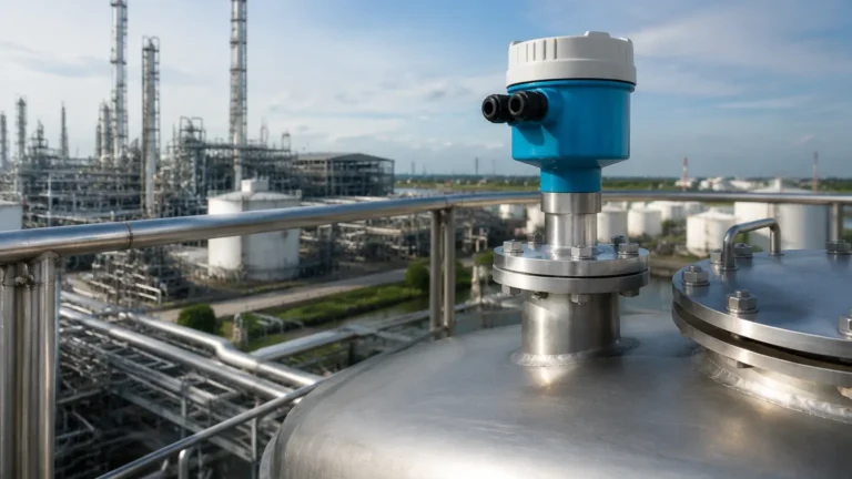
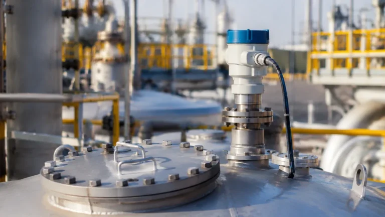
In the landscape of industrial automation, precision in level measurement is a critical factor for process safety, inventory management, and operational efficiency. Among the various technologies available, the jfr4 fmcw radar level transmitter represents a significant advancement in non-contact measurement. Utilizing Frequency Modulated Continuous Wave (FMCW) technology, these Radar Level Meters provide high-resolution data even in challenging environments characterized by dust, steam, or varying pressures.
This guide examines the technical principles, selection criteria, and installation requirements for the JFR4 series, providing engineers and procurement professionals with the factual basis needed for successful implementation.
1. Understanding the FMCW Measurement Principle
Before selecting a specific model, it is essential to understand how FMCW technology differs from traditional pulse radar. While pulse radar measures the time-of-flight of a discrete microwave pulse, FMCW radar transmits a continuous signal with a frequency that varies over time (a frequency sweep or "ramp").
The Frequency Sweep
The transmitter emits a high-frequency signal (typically in the 76 GHz to 81 GHz range for the JFR4 series) that increases linearly. When the signal hits the surface of the medium and reflects back to the antenna, there is a time delay. Because the transmitted frequency has continued to change during the signal's travel time, there is a frequency difference ($Δf$) between the emitted signal and the received signal.
Signal Processing
This frequency difference is directly proportional to the distance from the antenna to the material surface. By applying a Fast Fourier Transform (FFT) to the signal, the transmitter converts the frequency shift into a precise distance measurement. The primary advantage of FMCW over pulse radar is its significantly higher signal-to-noise ratio and better resolution, allowing it to distinguish between the true product level and false echoes from tank internals.
2. Technical Specifications and Selection Criteria
Choosing the correct jfr4 fmcw radar level transmitter requires a detailed analysis of the process medium and the vessel geometry. The JFR4 series is often preferred for its narrow beam angle and high dynamic range.
Selection Table: JFR4 Series Configurations
| Feature | Specification (Standard) | High-Temperature Variant |
| :— | :— | :— |
| Frequency Range | 76 GHz – 81 GHz | 76 GHz – 81 GHz |
| Measuring Range | Up to 30 m (98.4 ft) | Up to 120 m (393.7 ft) |
| Accuracy | ±2 mm (±0.078 in) | ±5 mm (±0.196 in) |
| Beam Angle | 3° to 8° (depending on antenna) | 3° to 6° |
| Process Temperature | -40°C to 80°C (-40°F to 176°F) | -40°C to 200°C (-40°F to 392°F) |
| Process Pressure | -1 to 3 bar (-14.5 to 43.5 psi) | -1 to 20 bar (-14.5 to 290 psi) |
| Output Signal | 4-20mA / HART / RS485 Modbus | 4-20mA / HART |
Key Selection Factors
1. Dielectric Constant (εr): The reflectivity of the medium depends on its dielectric constant. Materials with low εr (e.g., oils, plastic pellets) reflect less energy. The JFR4's high sensitivity allows it to measure materials with εr as low as 1.6, but for lower values, a guided wave radar might be required.
2. Antenna Type: Lens antennas are common in the JFR4 series because they are flush-mounted and resist buildup. For extremely dusty environments, a horn antenna with a dust cover or a purging connection is recommended.
3. Beam Angle: The 80 GHz frequency of the JFR4 allows for a very narrow beam. This is critical when installing in tall, narrow silos or tanks with internal obstructions like agitators or heating coils.
3. Installation Considerations and Constraints
Proper physical installation is the most significant factor in the long-term reliability of Radar Level Meters. Even the most advanced FMCW transmitter will fail if positioned incorrectly.
Nozzle Geometry
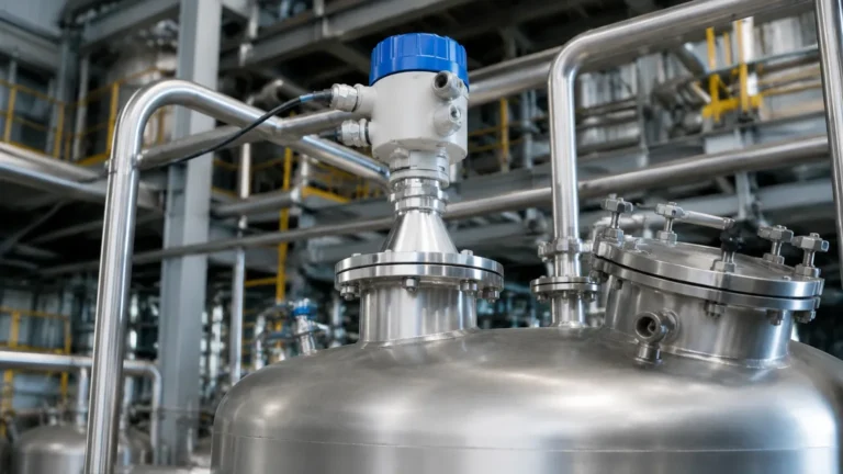
The nozzle height should be kept as short as possible. If the nozzle is too long or narrow, the radar signal may reflect off the internal edges of the nozzle before reaching the tank, creating a "dead zone" or a large false echo near the top of the tank. For the JFR4, the antenna should ideally extend slightly past the bottom of the nozzle.
Position and Orientation
* Avoid the Center: Never install the transmitter in the exact center of a domed tank, as this can concentrate parasitic reflections and cause signal interference.
* Wall Distance: Maintain a minimum distance from the tank wall (typically 200 mm to 500 mm / 8 in to 20 in) to prevent the beam from hitting the wall and losing energy.
* Inflow Avoidance: Ensure the beam does not cross the path of the material inflow, as falling liquid or solids will cause erratic readings.
Obstruction Management
If internal obstructions (ladders, pipes, agitators) are unavoidable, the JFR4's software allows for "False Echo Suppression." During commissioning, the engineer maps the empty tank, and the transmitter records the location of fixed reflections to ignore them during operation.
4. Application Risks and Environmental Factors
While the jfr4 fmcw radar level transmitter is robust, certain environmental conditions can introduce measurement risks.
Foam and Turbulence
Heavy, dense foam can absorb the microwave signal entirely, leading to a "loss of echo" error. If the process involves significant foaming, engineers should consider using a stilling well or a different frequency band. Surface turbulence (waves) can also scatter the signal, though the FMCW processing algorithms in the JFR4 are designed to average these fluctuations to maintain a steady output.
Dust and Condensation
In solid silos, heavy dust during filling can attenuate the signal. The 80 GHz signal of the JFR4 penetrates dust better than lower frequencies, but extreme buildup on the lens antenna can still be an issue. In such cases, a model with a PTFE (Teflon) lens or an integrated air purge system is necessary to keep the sensing face clean.
Temperature and Pressure Extremes
Standard JFR4 units are rated for moderate temperatures. If the process involves cryogenic liquids or high-pressure steam, specialized process seals and cooling fins must be specified to protect the electronics from thermal damage.
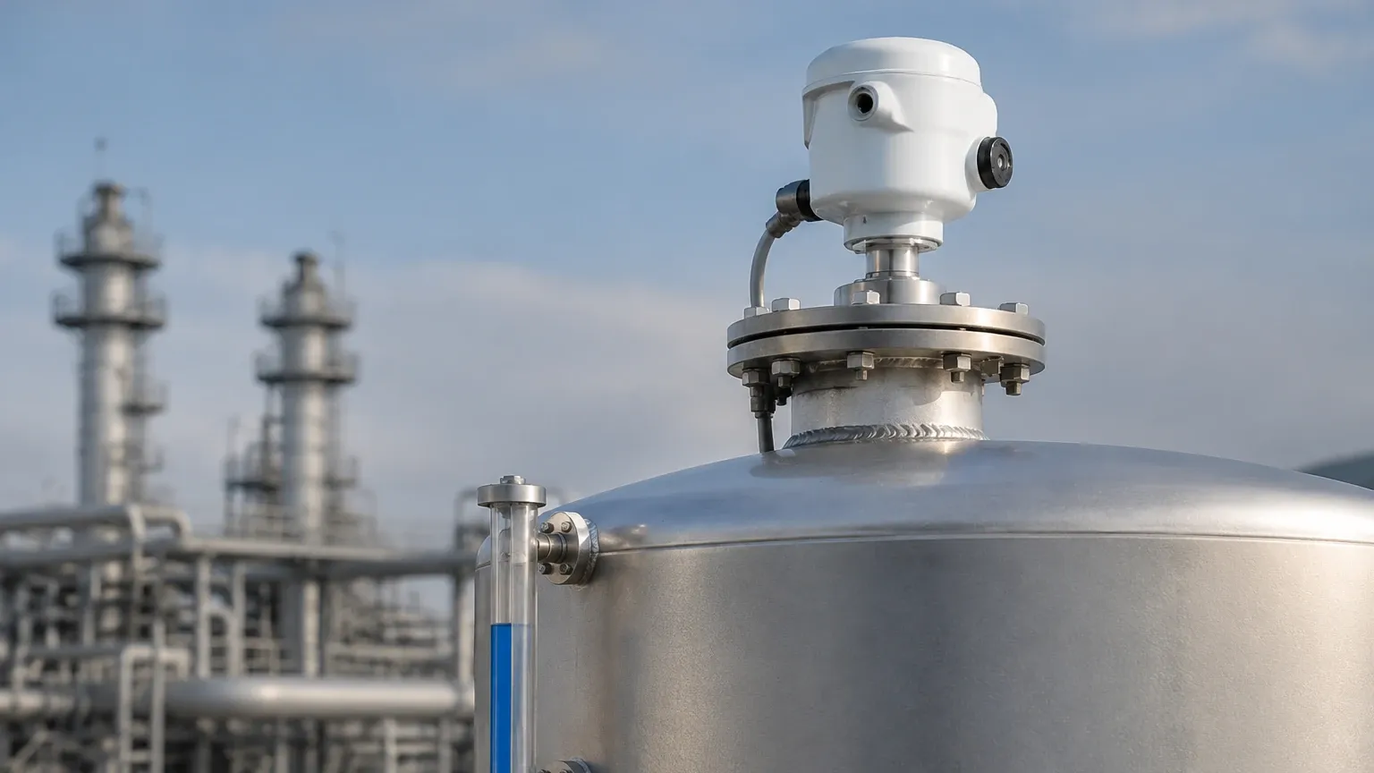
5. Information for International Buyers
When procuring a jfr4 fmcw radar level transmitter for a global project, several logistical and technical details must be confirmed with the manufacturer to ensure compatibility and compliance.
Certification and Compliance
* Hazardous Areas: Confirm if the site requires ATEX, IECEx, or CSA certification for explosive atmospheres. The JFR4 is available in Intrinsic Safety (Ex ia) and Explosion-Proof (Ex d) versions.
* Ingress Protection: For outdoor or wash-down environments, ensure the housing is rated at least IP66 or IP67.
Communication Protocols
Most modern plants utilize digital communication. Buyers should specify whether the unit needs to support HART 7.0, Foundation Fieldbus, Profibus PA, or RS485 Modbus. This ensures seamless integration into the existing Distributed Control System (DCS) or PLC architecture.
Documentation Requirements
Request a calibration certificate, material traceability reports (MTRs) for wetted parts (especially for chemical or food-grade applications), and a localized instruction manual. For international shipping, verify the Harmonized System (HS) code to facilitate customs clearance.
6. Frequently Asked Questions (FAQ)
Q: Can the JFR4 measure the level of solids and liquids?
A: Yes. The JFR4 FMCW radar is versatile and can be used for both liquids (water, chemicals, oils) and bulk solids (grain, plastic pellets, cement). However, the antenna configuration may change depending on the material's angle of repose.
Q: What is the minimum Dielectric Constant (εr) the JFR4 can detect?
A: In most standard applications, the JFR4 can reliably detect materials with a dielectric constant of εr ≥ 1.6. For materials below this, such as liquid nitrogen or certain dry powders, specialized sensitivity settings are required.
Q: Does the JFR4 require periodic recalibration?
A: Because it is a non-contact instrument with no moving parts, the JFR4 does not suffer from mechanical wear. Recalibration is typically not required unless mandated by local safety regulations or if the process medium changes significantly.
Q: How does the 80 GHz frequency compare to 26 GHz radar?
A: 80 GHz radar, like the JFR4, offers a much narrower beam and smaller antenna size. This makes it easier to install in small nozzles and provides better accuracy in tanks with complex internal structures. 26 GHz is still useful for applications with heavy foam or very long-range requirements in open spaces.
Conclusion
The jfr4 fmcw radar level transmitter is a high-performance solution for demanding industrial level measurement tasks. By leveraging the precision of 80 GHz FMCW technology, it overcomes many of the limitations associated with older pulse radar systems. Successful deployment depends on a thorough understanding of the measurement principle, careful selection of antenna and seal materials, and adherence to strict installation guidelines. For engineers seeking to optimize their process monitoring, these Radar Level Meters offer a reliable, low-maintenance path to achieving high-accuracy data in real-time.