Ag111
Ag111
In the landscape of industrial automation and process control, the Ag111 series represents a specialized class of high-frequency radar level measurement instruments. Designed to meet the rigorous demands of modern manufacturing, water treatment, and chemical processing, the Ag111 provides a non-contact solution for monitoring liquid and solid levels with high precision. As process engineers seek to optimize efficiency and safety, understanding the technical nuances, measurement principles, and installation requirements of the Ag111 is essential for successful system integration.
Understanding the Measurement Principles of Ag111
The Ag111 operates primarily on the principle of Time-of-Flight (ToF) using high-frequency microwave pulses. Unlike ultrasonic sensors that rely on sound waves—which are susceptible to variations in air temperature, pressure, and gas composition—the Ag111 utilizes electromagnetic waves, typically in the 26GHz or 80GHz range.
The Pulse Radar Mechanism
1. Emission: The antenna of the Ag111 emits a narrow microwave pulse toward the surface of the medium being measured.
2. Reflection: When the pulse hits the surface of the medium, a portion of the energy is reflected back toward the sensor. The strength of this reflection is largely determined by the dielectric constant (εr) of the material.
3. Reception: The sensor’s antenna receives the reflected signal.
4. Processing: The integrated microprocessor calculates the time elapsed between emission and reception. Since the speed of light is constant, the distance (D) can be calculated using the formula: D = (c × t) / 2, where 'c' is the speed of light and 't' is the travel time.
By subtracting this distance from the known total height of the vessel (the tank height), the instrument determines the exact level of the product. The Ag111 series is particularly valued for its ability to filter out "false echoes" caused by internal tank obstructions like agitators, ladders, or heating coils through advanced signal processing algorithms.
Technical Specifications and Selection Criteria
Selecting the correct Ag111 configuration requires an analysis of the process environment. Factors such as the physical state of the medium (liquid vs. solid), the presence of corrosive vapors, and the geometry of the storage vessel play a decisive role. For a broader look at how these instruments fit into a complete facility management strategy, professionals often consult the Main Page for technical documentation and compatibility charts.
Comparative Selection Table
| Feature | Ag111-L (Liquid Standard) | Ag111-S (Solids/Dust) | Ag111-C (Corrosive/Chemical) |
| :— | :— | :— | :— |
| Measuring Range | Up to 30 meters | Up to 70 meters | Up to 20 meters |
| Frequency | 26 GHz | 80 GHz | 26 GHz |
| Accuracy | ±2 mm | ±5 mm | ±3 mm |
| Process Temp. | -40°C to 150°C | -40°C to 250°C | -40°C to 120°C |
| Process Pressure | -0.1 to 4.0 MPa | -0.1 to 0.1 MPa | Vacuum to 1.6 MPa |
| Antenna Material | Stainless Steel 316L | Reinforced Polymer/SS | PTFE / PVDF |
| Signal Output | 4-20mA / HART | 4-20mA / HART / Modbus | 4-20mA / HART |
When evaluating these specifications, engineers must prioritize the dielectric constant of the medium. Materials with a low dielectric constant, such as hydrocarbons or liquefied gases, reflect less energy, potentially requiring the Ag111 to be equipped with a larger antenna or a specialized stilling well to concentrate the signal.
Installation and Engineering Considerations
The reliability of an Ag111 installation is heavily dependent on its placement relative to the vessel's internal structure. Improper mounting is the leading cause of signal interference and measurement drift.
1. Nozzle Geometry
The mounting nozzle should be as short as possible. If the nozzle is too long or too narrow, the radar beam may interact with the nozzle walls, creating a "ringing" effect that masks the true level signal near the top of the tank. Ideally, the antenna should extend at least 10mm beyond the bottom of the nozzle.
2. Avoiding Obstructions
The radar beam propagates in a cone shape. Any metal structures (pipes, ladders, or braces) within this cone will reflect the signal. While the Ag111 software can perform a "false echo suppression" to ignore these fixed reflections, it is best practice to install the unit at least 200mm to 500mm away from the tank wall to minimize interference.
3. Agitators and Turbulence
In tanks with active mixing, the surface of the liquid may be turbulent or vortexed. The Ag111 handles this through software damping, which averages the level readings over a set period. However, if the agitation creates heavy foam, the microwave signal may be absorbed rather than reflected. In such cases, a guided wave radar or a hydrostatic transmitter might be recommended as an alternative.
4. Orientation
For solid materials, the Ag111 should be mounted with an adjustable flange. This allows the sensor to be aimed at the "angle of repose" of the material pile, ensuring the maximum amount of energy is reflected back to the antenna rather than scattered away.
Application-Specific Advantages of the Ag111
The Ag111 is not a one-size-fits-all tool; rather, it excels in specific B2B industrial contexts where contact-based measurement is impractical.
* Chemical Processing: In tanks containing sulfuric acid or caustic soda, contact sensors (like floats or pressure diaphragms) often suffer from corrosion. The Ag111-C variant, featuring a full PTFE wetted part construction, remains completely isolated from the medium, extending the service life significantly.
* Water and Wastewater: For open channel flow or large reservoir monitoring, the Ag111 provides a maintenance-free alternative to ultrasonic sensors. It is unaffected by wind, fog, or temperature fluctuations over the water surface, providing consistent data for SCADA systems.
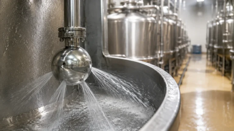
* Food and Beverage: With hygienic flange connections and stainless steel housings, the Ag111 supports CIP (Clean-In-Place) processes. The non-contact nature ensures there is no risk of product contamination from the sensor itself.
Limitations and Operational Constraints
While the Ag111 is highly versatile, engineers must be aware of its physical and electronic limitations:
* Dielectric Threshold: If the medium has a dielectric constant (εr) lower than 1.4, the reflection may be too weak for standard Ag111 units. A bypass pipe or stilling well is required to boost the signal-to-noise ratio.
* Heavy Foam: Dense, thick foam (such as that found in certain fermentation processes) can act as an insulator, absorbing the radar pulse. If the foam is light and airy, the radar will pass through it and measure the liquid level; however, dense foam may be detected as the "level" itself or cause a complete loss of signal.
* Vacuum Conditions: While radar waves travel perfectly in a vacuum, the physical seals of the Ag111 must be rated for vacuum pressure to prevent air ingress or damage to the internal electronics.
Maintenance and Long-term Reliability
One of the primary selling points of the Ag111 is its low maintenance requirement. Because there are no moving parts to wear out or clog, the primary maintenance task is periodic verification of the signal quality.
1. Visual Inspection: Check the antenna for buildup of condensate or crystallized product. While many Ag111 units feature a "drip-off" antenna design, extreme buildup can still attenuate the signal.
2. Signal-to-Noise Ratio (SNR) Monitoring: Using HART communication, operators can monitor the SNR. A declining ratio often indicates that the antenna needs cleaning or that the internal electronics are reaching the end of their lifecycle.
3. Recalibration: Under stable conditions, the Ag111 does not require frequent recalibration. However, if the process medium changes significantly (e.g., switching from a high-dielectric liquid to a low-dielectric one), the sensitivity settings may need adjustment.
Frequently Asked Questions (FAQ)
Q: Can the Ag111 measure through a plastic tank lid?
A: Yes. Since plastic is non-conductive and has a low dielectric constant, microwaves can pass through it. This allows the Ag111 to measure the level inside a plastic IBC or storage tank without cutting a hole in the lid, provided the plastic is not carbon-filled or metallic-coated.
Q: How does the Ag111 compare to ultrasonic sensors in terms of cost-effectiveness?
A: While the initial purchase price of an Ag111 radar meter is typically higher than an ultrasonic sensor, the total cost of ownership is often lower in complex environments. The Ag111's immunity to temperature, pressure, and vapor changes reduces the need for frequent troubleshooting and manual measurements.
Q: Is the Ag111 suitable for high-dust environments like grain silos?
A: The 80GHz version of the Ag111 is specifically designed for these applications. The high frequency allows for a very narrow beam angle, which can penetrate dust clouds more effectively than lower-frequency models and avoid reflections from the silo walls.
Q: What power supply is required for the Ag111?
A: Most models are 2-wire, loop-powered units requiring 12-36V DC. This simplifies wiring as the same pair of wires carries both the power and the 4-20mA signal.
By carefully considering these technical factors, procurement officers and plant engineers can ensure that the Ag111 provides the reliable data necessary for optimized industrial operations. For further technical support or to view specific model variants, visiting the Main Page is recommended to align equipment specifications with project-specific requirements.