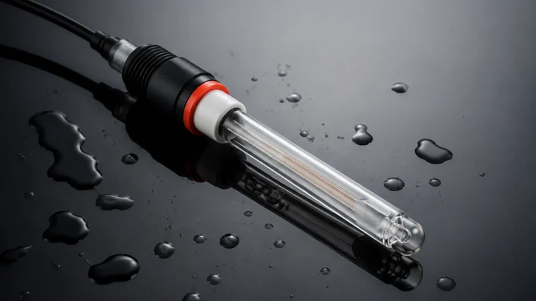
Digital Conductivity Meter
Digital Conductivity Meter
In industrial process control, the measurement of electrolytic conductivity serves as a critical indicator of water purity, chemical concentration, and the presence of dissolved solids. A digital conductivity meter is a sophisticated analytical instrument designed to measure the ability of a solution to conduct an electrical current. Unlike traditional analog systems, digital meters utilize advanced microprocessors to convert raw sensor signals into precise, temperature-compensated data, often transmitted via digital protocols for integration into SCADA or PLC systems.
For industrial operators and engineers, selecting the right analytical tools is as vital as choosing reliable level measurement hardware. For a comprehensive overview of industrial instrumentation and integrated measurement solutions, professionals often refer to the Main Page of specialized manufacturers like Welk to ensure system compatibility.
1. Measurement Principles of Digital Conductivity Meters
Conductivity is the reciprocal of electrical resistivity. In a liquid, current is carried by ions. Therefore, as the concentration of ions increases, the conductivity of the solution increases. The basic unit of measurement is Siemens per meter (S/m), though industrial applications typically use microsiemens per centimeter (µS/cm) or millisiemens per centimeter (mS/cm).
The Role of the Cell Constant (K)
Every conductivity sensor has a specific geometry defined by the "cell constant" ($K$). The cell constant is the ratio of the distance between the electrodes ($L$) to the cross-sectional area of the electrodes ($A$):
$$K = L / A$$
* Low Cell Constants (e.g., K=0.01 or 0.1): Used for high-purity water where the distance between electrodes is small or the area is large to capture weak signals.
* High Cell Constants (e.g., K=1.0 or 10.0): Used for concentrated chemicals or wastewater where electrodes must be spaced further apart to prevent current saturation.
A digital conductivity meter stores these constants in its memory, allowing for automatic calculation and high-precision output regardless of sensor wear or replacement.
Contacting vs. Inductive Measurement
There are two primary methods used by a digital conductivity meter to interface with the process fluid:
1. Contacting Sensors: These utilize two or four electrodes that come into direct contact with the liquid. They are highly sensitive and ideal for low-conductivity applications like pure water or boiler condensate. However, they are susceptible to fouling and polarization.
2. Inductive (Toroidal) Sensors: These use two wire-wound metal toroids encapsulated in a plastic housing (such as PEEK or PFA). One coil induces an electric current in the liquid, and the second coil measures the magnitude of that current. Since there are no exposed electrodes, these are immune to fouling, corrosion, and polarization, making them the standard for harsh chemical processes and wastewater.
2. Technical Selection Criteria for Industrial Applications
Selecting a digital conductivity meter requires an evaluation of the process environment and the required accuracy. The following table provides a guideline for sensor selection based on common industrial scenarios:
| Application | Conductivity Range | Recommended Sensor Type | Typical Material |
| :— | :— | :— | :— |
| Ultrapure Water / RO | 0.055 – 20 µS/cm | Contacting (2-pole) | 316L Stainless Steel |
| Cooling Tower Water | 100 – 5,000 µS/cm | Contacting (4-pole) | Graphite / Epoxy |
| Chemical Concentration | 10 – 2,000 mS/cm | Inductive (Toroidal) | PEEK / PFA |
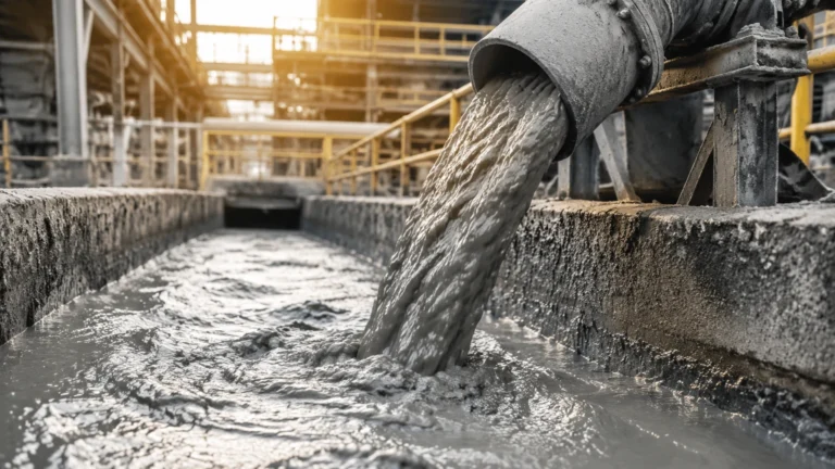
| Wastewater Treatment | 500 – 10,000 µS/cm | Inductive (Toroidal) | Polypropylene |
| Food & Beverage (CIP) | 1 – 500 mS/cm | Inductive (Hygienic) | Food-grade PEEK |
Temperature Compensation
Conductivity is highly dependent on temperature; for most aqueous solutions, conductivity increases by approximately 2% per degree Celsius. A high-quality digital conductivity meter must include an integrated temperature sensor (typically a Pt100 or Pt1000 RTD) and utilize Automatic Temperature Compensation (ATC). The meter references the reading to a standard temperature, usually 25°C (77°F), to provide consistent data regardless of process fluctuations.
3. Installation Considerations and Best Practices
To ensure the accuracy of a digital conductivity meter, proper mechanical and electrical installation is mandatory. Poor placement can lead to air entrapment or signal interference.
Mechanical Placement
* Full Pipe Flow: The sensor must always be completely submerged in the liquid. For horizontal pipes, install the sensor on the side or bottom to avoid air pockets at the top. In vertical pipes, an upward flow direction is preferred to ensure the pipe remains full.
* Avoid Dead Zones: Ensure the sensor is placed in a high-velocity area where the fluid is representative of the entire process. Avoid stagnant areas near elbows or T-junctions.
* Inductive Clearance: For inductive (toroidal) sensors, maintain at least 30 mm (approx. 1.2 inches) of clearance from pipe walls or other metallic objects, as the electromagnetic field can be distorted by nearby metal, leading to measurement errors.
Electrical and Signal Integration
Modern digital conductivity meters often provide multiple output options:
* 4-20mA Analog: Standard for traditional PLC integration.
* Modbus RTU / RS485: Allows for long-distance digital communication and multiple parameter transmission (Conductivity + Temperature + TDS).
* HART Protocol: Enables digital communication over existing 4-20mA wiring, useful for remote diagnostics and calibration.
4. Maintenance and Calibration Procedures
While digital systems are more stable than analog predecessors, regular maintenance is required to combat sensor fouling and electronic drift.
Cleaning the Sensor
* Contacting Sensors: If the electrodes are coated with scale or oil, the measured conductivity will drop. Clean with a mild detergent or a 5% hydrochloric acid solution, followed by a thorough rinse with deionized water.
* Inductive Sensors: These require less frequent cleaning, but heavy sludge or biological growth should be removed to prevent the center "bore" of the toroid from clogging.
Calibration Steps
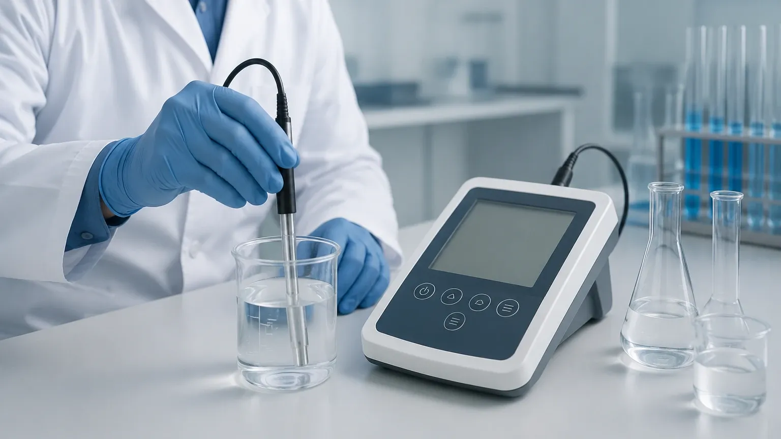
Calibration should be performed using certified conductivity standard solutions.
1. Zero Calibration: Perform this in dry air to ensure the meter reads zero when no conductivity is present.
2. Slope Calibration: Submerge the cleaned sensor in a standard solution (e.g., 1413 µS/cm). Allow the temperature to stabilize before adjusting the meter to match the standard value.
3. Verification: Check the reading against a second, different standard solution to ensure linearity across the expected measurement range.
5. Limitations and Potential Risks
Despite their versatility, digital conductivity meters have specific limitations that engineers must account for during the design phase:
* Polarization: In contacting sensors, the accumulation of ions at the electrode surface can create a "back-EMF," resulting in falsely low readings. Digital meters mitigate this by using high-frequency AC drive signals, but it remains a risk in high-conductivity liquids if the wrong cell constant is used.
* Non-Specific Measurement: Conductivity is a "bulk" measurement. It tells you the total ionic content but cannot distinguish between different types of ions (e.g., it cannot tell the difference between NaCl and NaOH). If specific chemical identification is required, chromatography or titration may be necessary.
* Material Compatibility: The sensor body and O-rings must be compatible with the process fluid. For example, PEEK is excellent for high temperatures and acids, but may not be suitable for certain highly concentrated oxidizing agents.
6. Frequently Asked Questions (FAQ)
Q: How often should I calibrate my digital conductivity meter?
A: In stable water treatment applications, quarterly calibration is often sufficient. In harsh chemical processes or CIP systems, monthly or even weekly verification may be required depending on the rate of sensor fouling.
Q: Can a digital conductivity meter measure Total Dissolved Solids (TDS)?
A: Yes. Most digital meters have a built-in TDS conversion function. They multiply the conductivity reading by a factor (typically between 0.5 and 0.7) to estimate the TDS in ppm (parts per million) or mg/L.
Q: Why is my conductivity reading jumping around?
A: This is often caused by air bubbles passing through the sensor or electrical interference (EMI) from nearby high-power motors or VFDs. Ensure the sensor is properly grounded and that the cable is shielded and separated from power lines.
Q: What is the difference between "Conductivity" and "Resistivity"?
A: They are mathematical inverses. Resistivity (measured in MΩ·cm) is typically used for ultrapure water applications, while conductivity is used for general water and chemical applications.
Conclusion
A digital conductivity meter is an indispensable tool for modern industrial automation, providing the data necessary to optimize chemical dosing, protect boiler systems, and ensure product quality. By understanding the differences between contacting and inductive technologies and adhering to strict installation and calibration protocols, facilities can achieve reliable, long-term performance. For those looking to integrate these analytical measurements with broader tank and vessel management systems, exploring the Main Page of industry-leading suppliers like Welk provides access to the necessary technical documentation and product specifications to build a robust control architecture.