Differential Pressure Sensors
Differential Pressure Sensors
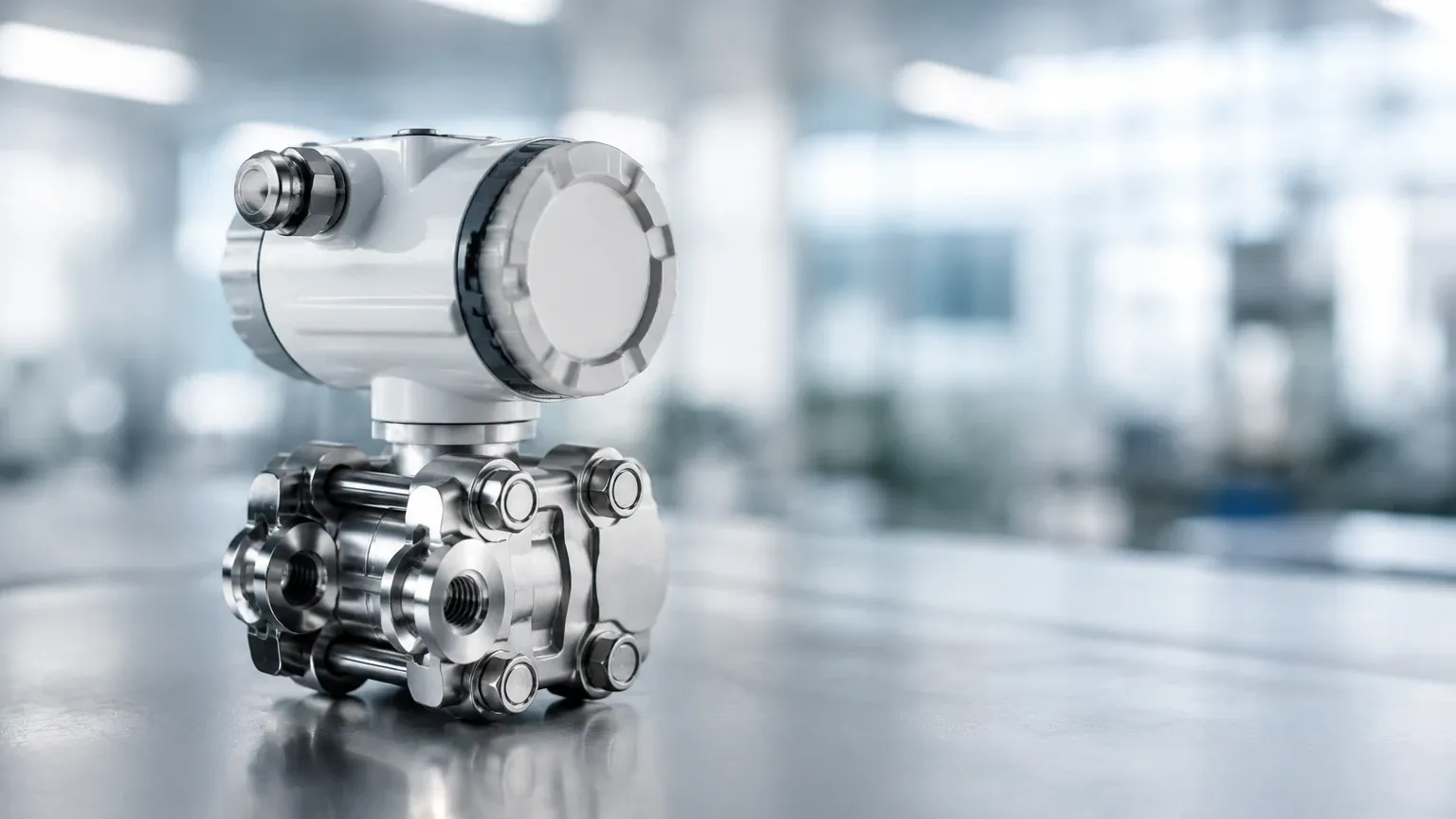
In the landscape of industrial automation and process control, differential pressure sensors represent one of the most versatile and widely implemented technologies for monitoring fluid dynamics. While pressure measurement is a broad field, the specific ability to measure the difference between two points—rather than a single point relative to atmospheric pressure—allows these instruments to derive critical data such as liquid level, flow rate, and filter health. For engineers and facility managers, understanding the nuances of differential pressure (DP) technology is essential for ensuring operational efficiency and safety in environments ranging from water treatment plants to complex chemical refineries.
Fundamental Principles of Differential Pressure Measurement
At its core, a differential pressure sensor functions by detecting the physical force exerted by a process medium on two separate sensing elements, typically diaphragms, and calculating the mathematical difference between them. This is expressed by the formula:
$$\Delta P = P_1 – P_2$$
Where $P_1$ is the high-pressure side and $P_2$ is the low-pressure side.
Sensing Mechanisms
Most modern industrial differential pressure sensors utilize one of three primary sensing technologies:
1. Piezoresistive Sensors: These utilize a silicon or ceramic diaphragm with integrated strain gauges. When pressure deforms the diaphragm, the electrical resistance of the gauges changes. This change is proportional to the pressure and is converted into a standardized electrical signal (e.g., 4-20mA).
2. Capacitive Sensors: These involve a sensing diaphragm positioned between two fixed capacitor plates. As the diaphragm moves due to pressure differences, the capacitance changes. This method is highly sensitive and is often preferred for low-pressure ranges.
3. Inductive/LVDT: Used less frequently in standard process level applications but common in high-precision laboratory settings, these measure the displacement of a core within a magnetic field.
In the context of level measurement, the sensor relies on the principle of hydrostatic pressure. The pressure exerted by a liquid column is directly proportional to its height ($h$) and its density ($\rho$), governed by the equation $P = \rho gh$. By measuring the pressure at the bottom of a vessel and comparing it to the pressure at the top, the sensor can determine the height of the liquid regardless of the internal tank pressure.
Application in Liquid Level Measurement
Differential pressure sensors are the industry standard for level measurement in closed, pressurized vessels. Unlike simple hydrostatic transmitters that measure pressure relative to the atmosphere, DP sensors compensate for the "blanket pressure" or vapor pressure existing above the liquid.
Open vs. Closed Tanks
* Open Tanks: In an atmospheric tank, the low-pressure side ($P_2$) of the sensor is vented to the atmosphere. The sensor effectively measures the weight of the liquid column above the high-pressure port.
* Closed/Pressurized Tanks: In vessels containing pressurized gas or steam (such as a boiler or a chemical reactor), the low-pressure side must be connected to the top of the tank. This ensures that the static pressure of the gas is subtracted from the total pressure at the bottom, leaving only the pressure exerted by the liquid column.
Wet Leg vs. Dry Leg
When the low-pressure side of the sensor is connected to the top of a pressurized tank, the connecting line (impulse line) can either be filled with gas (Dry Leg) or a reference liquid (Wet Leg).
* Dry Leg: Used when the gas at the top of the tank will not condense at ambient temperatures.
* Wet Leg: Used when vapors are likely to condense into liquid. The line is intentionally filled with a known liquid to prevent erratic readings caused by random condensation accumulation.
Technical Selection Criteria for Industrial Applications
Selecting the correct differential pressure sensor requires a thorough analysis of the process environment. Failure to account for chemical compatibility or pressure spikes can lead to premature instrument failure or inaccurate data.
| Criteria | Considerations | Typical Range/Options |
| :— | :— | :— |
| Pressure Range | The maximum expected differential and static pressure. | 0.1 mbar to 400 bar (0.0015 to 5800 psi) |
| Wetted Materials | Compatibility with the process fluid to prevent corrosion. | 316L Stainless Steel, Hastelloy C, Tantalum, Monel |
| Accuracy Class | The required precision for the specific process. | 0.075%, 0.1%, or 0.5% of span |
| Temperature Limits | Process and ambient temperature operating ranges. | -40°C to +120°C (-40°F to 248°F) |
| Output Signal | Integration with the local control system (PLC/DCS). | 4-20mA, HART, Modbus RTU, Profibus |
| Process Connection | Physical mounting requirements. | 1/2" NPT, Flanged (ANSI/DIN), Sanitary Tri-clamp |
For specialized requirements, manufacturers like Welk provide customized OEM/ODM services to ensure the sensor housing and electronics meet specific hazardous area certifications (ATEX/IECEx) or sanitary standards for the food and pharmaceutical industries.
Installation Best Practices
The reliability of differential pressure sensors is heavily dependent on the quality of the installation. Even the most accurate sensor will provide false data if the impulse lines are incorrectly configured.
1. Impulse Line Slope: Impulse lines should always be sloped (at least 1:12 ratio) to allow gas bubbles to escape back into the tank (for liquid service) or to allow condensate to drain back into the tank (for gas service).
2. Manifold Valves: A 3-way or 5-way valve manifold is essential. These allow the sensor to be isolated, vented, and zero-checked without shutting down the entire process. A 5-way manifold includes additional bleed valves for clearing debris or trapped air.
3. Mounting Orientation: Sensors should be mounted below the process taps for liquid applications to ensure the lines remain full, and above the process taps for gas applications to keep the lines dry.
4. Temperature Compensation: In outdoor installations, heat tracing or insulation may be required for impulse lines to prevent freezing or significant density changes in the reference leg fluid.
Limitations and Common Challenges
While differential pressure sensors are robust, they are not "set and forget" instruments. Engineers must be aware of the following limitations:
* Density Sensitivity: Since DP sensors measure mass (weight), any change in the liquid's density—caused by temperature fluctuations or changes in chemical concentration—will result in a level measurement error. If the density decreases, the sensor will report a lower level than actually exists.
* Clogging and Sedimentation: In applications involving slurries or viscous fluids, impulse lines can become clogged. In these cases, Diaphragm Seals (remote seals) are used. These seals use a flexible membrane and a capillary tube filled with silicone oil to transmit pressure to the sensor, keeping the process fluid out of the instrument internals.
* Static Pressure Limits: Every DP sensor has a maximum static pressure rating. Exceeding this can damage the internal sensing element, even if the differential pressure itself remains within the calibrated range.
Frequently Asked Questions (FAQ)
Q: How often should differential pressure sensors be calibrated?
A: In most industrial applications, an annual calibration check is standard. However, in critical safety loops or high-temperature processes, semi-annual or quarterly checks may be necessary to account for sensor drift.
Q: Can a DP sensor measure the level of a solid, like grain or powder?
A: Generally, no. Differential pressure sensors rely on the fluid properties of liquids to exert hydrostatic pressure. For solids, ultrasonic, radar, or laser level meters are more appropriate.
Q: What is the difference between a pressure transmitter and a differential pressure transmitter?
A: A standard pressure transmitter has one process connection and measures pressure relative to a vacuum or the atmosphere. A differential pressure transmitter has two connections (High and Low) and measures the difference between them.
Q: How do I handle applications with high-temperature fluids?
A: Use remote diaphragm seals with capillary tubes. The capillaries allow the sensor electronics to be mounted away from the heat source, while the fill fluid transmits the pressure accurately.
Conclusion and Selection Support
Differential pressure sensors remain a cornerstone of industrial level and flow measurement due to their proven reliability and theoretical simplicity. By understanding the relationship between pressure, density, and height, and by adhering to strict installation protocols regarding impulse lines and manifolds, process engineers can achieve high levels of accuracy in even the most demanding pressurized environments.
When evaluating hardware for a new project or replacing legacy systems, it is vital to consult with a professional manufacturer that offers a broad range of materials and configurations. For detailed technical specifications, application-specific advice, or to explore a full catalog of industrial level measurement instruments, professionals are encouraged to Review product options and application support on the Welk official site. Accessing the Main Page provides comprehensive data on radar, ultrasonic, and hydrostatic solutions alongside differential pressure technologies, ensuring the right tool is selected for your specific industrial automation needs.