Level Sensor for Solid
Level Sensor for Solid
In industrial process automation, measuring the level of bulk solids presents a unique set of challenges compared to liquid level measurement. While liquids maintain a horizontal surface and a consistent density, solids are characterized by irregular surfaces, dust generation, varying bulk densities, and the "angle of repose." Selecting the correct level sensor for solid applications requires a deep understanding of the material properties and the physical environment of the silo or bin.
This guide examines the principles of operation for various solid level measurement technologies, provides engineering selection criteria, and outlines installation best practices to ensure reliable process control.
Understanding the Physics of Solids Measurement
Before selecting an instrument, it is essential to understand how solids behave within a storage vessel. Unlike liquids, which exert pressure equally in all directions and settle flat, solids possess internal friction. This leads to several phenomena that affect sensor performance:
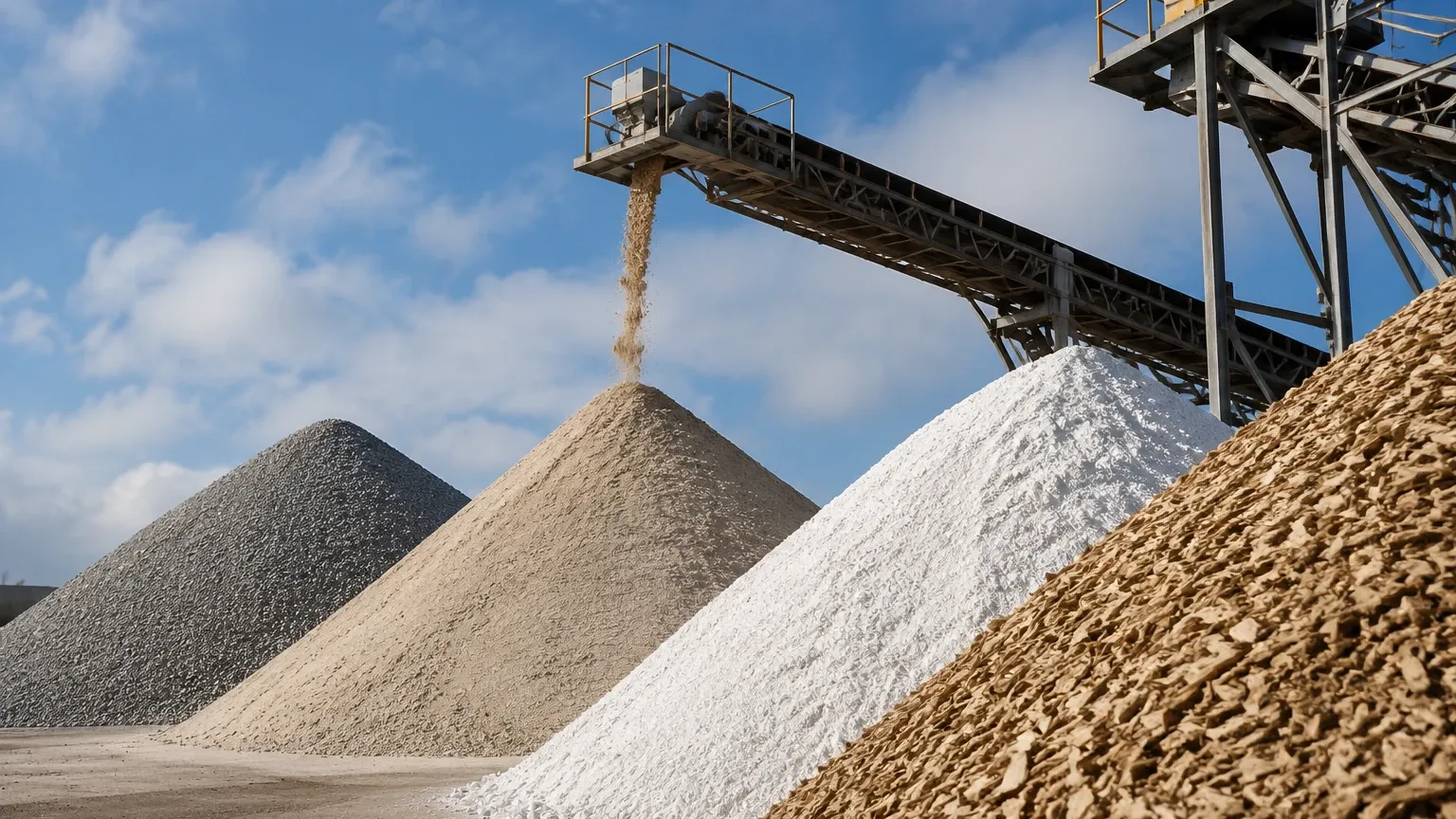
1. Angle of Repose: When solids are poured into a vessel, they form a cone-shaped pile. The angle between the horizontal plane and the slope of the pile is the angle of repose. During discharge, an inverted cone (funnel flow) often forms. A level sensor must be able to account for these uneven surfaces.
2. Bulk Density: This is the mass per unit volume of the material, including the air between particles. Changes in bulk density can affect the pressure exerted on hydrostatic sensors or the vibration damping on tuning fork switches.
3. Dielectric Constant (εr): For radar and capacitance sensors, the ability of the material to reflect or store electrical energy is critical. Materials with low dielectric constants (like plastic pellets or dry lime) are harder to detect than those with high dielectric constants.
4. Dust and Vapor: Many solid processes, such as cement or flour production, generate significant dust. This can attenuate ultrasonic signals and coat sensor faces, leading to signal loss.
Measurement Principles and Technologies
Level measurement for solids is generally categorized into non-contact and contact methods, as well as continuous and point-level detection.
1. Non-Contact Radar (FMCW)
Radar level transmitters are widely considered the gold standard for continuous level sensor for solid applications. They operate on the Time of Flight (ToF) principle using Frequency Modulated Continuous Wave (FMCW) technology.
Principle: The sensor emits a high-frequency microwave signal that sweeps across a frequency range. The signal reflects off the solid surface and returns to the antenna. The difference in frequency between the emitted and received signal is proportional to the distance.
* 80GHz Technology: Modern radar sensors often utilize the 80GHz frequency band. This allows for a very narrow beam angle (as small as 3°), which is crucial for solids. A narrow beam can avoid internal obstructions like ladders or reinforcement struts and provides a stronger return signal from the angled surface of a solid cone.
* Advantages: Immune to dust, temperature fluctuations, and vacuum. No moving parts.
* Limitations: Extremely low dielectric materials may require specialized high-sensitivity units.
2. Ultrasonic Level Sensors
Ultrasonic sensors use sound waves to measure distance. The transducer emits an ultrasonic pulse that bounces off the material surface and returns.
Principle: The distance is calculated based on the speed of sound. Since the speed of sound varies with air temperature, these sensors include integrated temperature compensation.
* Advantages: Cost-effective for short to medium ranges in non-dusty environments.
* Limitations: Sound waves are mechanical and are easily absorbed or scattered by heavy dust, foam, or irregular surfaces. They are generally not recommended for tall silos containing fine powders.
3. Guided Wave Radar (GWR)
Guided Wave Radar is a contact-based technology that uses a cable or rod probe to guide the microwave signal to the material.
Principle: The signal travels along the probe until it hits the medium, where a change in the dielectric constant causes a reflection.
* Advantages: Highly reliable for materials with low dielectric constants because the signal is concentrated around the probe. It is unaffected by dust or heavy steam.
* Limitations: The main risk in solid applications is the mechanical "pull force" exerted on the probe. In tall silos, the downward friction of settling solids can pull with forces exceeding several tons, potentially ripping the probe from the silo roof. Heavy-duty cables and robust mounting are required.
4. Rotary Paddle Switches (Point Level)
For simple high-level (overfill) or low-level (dry run) detection, the rotary paddle is a mechanical staple.
Principle: A small motor slowly rotates a paddle. When the solid material reaches the paddle, it stalls the motor, which triggers a microswitch to signal the level state.
* Advantages: Simple, inexpensive, and unaffected by the electrical properties of the material.
* Limitations: Subject to mechanical wear and tear. Not suitable for very light powders that cannot stall the motor or for heavy rocks that might break the paddle.
Technical Selection Criteria
Choosing the right level sensor for solid involves matching the technology to the specific material and vessel characteristics. For a detailed look at specific instrument specifications and performance data, engineers should consult the Main Page of the manufacturer's technical catalog.
| Feature | 80GHz Radar | Ultrasonic | Guided Wave Radar | Rotary Paddle |
| :— | :— | :— | :— | :— |
| Measurement Type | Continuous | Continuous | Continuous | Point Level |
| Max Range | Up to 120m | Up to 30m | Up to 75m | N/A |
| Dust Tolerance | Excellent | Poor | Excellent | Excellent |
| Accuracy | ±2mm | ±0.25% of range | ±5mm | N/A |
| Contact/Non-contact | Non-contact | Non-contact | Contact | Contact |
| Relative Cost | High | Medium | Medium | Low |
Installation Considerations for Solids
Proper installation is as important as technology selection. Because solids do not form a flat surface, the placement of the sensor significantly impacts the accuracy of the reading.
Mounting Position
To obtain a representative level reading, the sensor should typically be mounted at 1/6th of the silo diameter from the wall. Mounting too close to the wall can cause interference from the silo sides, while mounting directly over the fill point will result in erratic readings due to the falling material stream and the peak of the cone.
Beam Angle and Obstructions
When using non-contact sensors, the "beam cone" must be kept clear of internal structures. If a 26GHz radar with a 10° beam angle is used in a narrow silo, the signal may hit the walls or internal braces before reaching the bottom. Switching to an 80GHz sensor with a 3° beam angle often resolves these issues.
Aiming Flanges
For solids with a very steep angle of repose, the reflected signal might bounce away from the sensor antenna. Using an adjustable aiming flange (gimbal mount) allows the technician to tilt the sensor toward the middle of the material slope, ensuring a stronger return echo.
Nozzle Dimensions
The mounting nozzle should be as short as possible. If the nozzle is too long or narrow, the sensor may detect the edge of the nozzle as the "top" of the material (the "ringing" effect). This is particularly problematic for ultrasonic and lower-frequency radar sensors.
Limitations and Common Risks
* The "Rat-Hole" Effect: In some silos, material clings to the walls while the center empties, creating a hole. A single-point sensor might indicate the silo is empty while significant material remains on the sides.
* Static Electricity: Fine powders moving at high speeds can generate significant static charges. Sensors used in these environments must be properly grounded and, in many cases, ATEX/IECEx certified for explosive dust atmospheres (Class II, Div 1/2).
* Acoustic Noise: In pneumatic filling systems, the high-velocity air creates significant acoustic noise that can interfere with ultrasonic sensors.
Frequently Asked Questions (FAQs)
Q: Can I use a liquid radar sensor for solids?
A: While the basic principle is the same, sensors designed specifically for solids typically have more powerful processors to handle weak, scattered echoes and specialized algorithms to track the moving surface of a cone. It is recommended to use a dedicated solid level sensor.
Q: How do I measure level in a silo with a lot of internal bracing?
A: An 80GHz radar is the best choice due to its narrow beam. Additionally, most modern transmitters offer "False Echo Suppression" or "Background Mapping," where the sensor is programmed to ignore static reflections from known internal obstructions.
Q: What is the best sensor for extremely light powders like fumed silica?
A: Fumed silica has an extremely low dielectric constant and very low bulk density. Guided Wave Radar with a large surface area probe or high-sensitivity 80GHz radar are the most reliable options. Point level detection is often best handled by vibrating rod sensors tuned for low-density materials.
Q: Does moisture content affect the measurement?
A: For radar, increased moisture typically increases the dielectric constant, which actually makes the material easier to detect. However, moisture can also cause material to clump or stick to the sensor face, which may require the use of a dust cover or an air purge system to keep the antenna clean.
For further engineering support and to review specific product options for your application, visit the Main Page for comprehensive technical documentation.