Continuous Level Sensor
Continuous Level Sensor
In modern industrial automation, the ability to monitor the exact volume or height of a substance within a tank or silo is critical for operational efficiency, safety, and inventory management. A continuous level sensor provides a real-time, uninterrupted signal representing the level of the material, as opposed to point-level sensors (switches) which only indicate if a substance has reached a specific threshold. This article explores the fundamental principles of continuous level measurement, compares leading technologies, and provides engineering guidelines for selection and installation.
Understanding Continuous Level Measurement
Continuous level measurement involves the constant tracking of the liquid or solid level in a vessel. The sensor converts the physical level into an electrical signal—typically a 4-20 mA analog output, or digital protocols such as Modbus, HART, or Foundation Fieldbus. This data allows control systems (PLCs or DCS) to perform complex tasks like automated pump control, batch processing, and high-accuracy inventory forecasting.
Selecting the appropriate continuous level sensor requires an understanding of the physical properties of the medium (density, dielectric constant, viscosity), the process conditions (temperature, pressure, turbulence), and the physical constraints of the vessel. For a comprehensive overview of available technologies, engineers often consult the Main Page of specialized instrumentation manufacturers to compare performance specifications.
Core Technologies and Measurement Principles
Before selecting a sensor, it is essential to understand how different technologies interact with the process material. Each principle has inherent strengths and limitations.
Radar Level Measurement
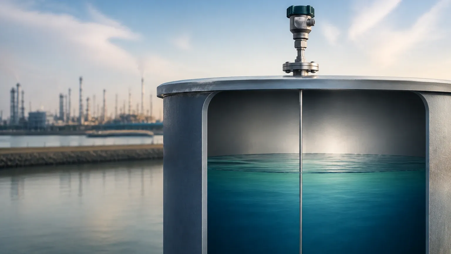
Radar sensors are among the most versatile tools for continuous level monitoring. They generally fall into two categories: Non-contact (Free-space) Radar and Guided Wave Radar (GWR).
* Non-contact Radar: These sensors emit high-frequency electromagnetic pulses (typically in the 26 GHz or 80 GHz range). The pulses reflect off the surface of the medium and return to the sensor. The device measures the "Time of Flight" (ToF) or the frequency shift (FMCW) to calculate the distance. Because radar waves do not require a medium for travel, they are unaffected by vacuum, temperature fluctuations, or high pressure.
* Guided Wave Radar (GWR): GWR utilizes a physical probe (rod or cable) to guide the microwave pulse to the material surface. When the pulse hits the surface, a change in the dielectric constant causes a reflection. GWR is particularly effective in applications with low dielectric constants or where internal obstructions might interfere with a free-space signal.
Ultrasonic Level Measurement
Ultrasonic sensors operate on the principle of acoustic reflection. The sensor head emits an ultrasonic pulse that travels through the air, hits the surface of the liquid or solid, and bounces back. The distance is calculated based on the speed of sound.
While cost-effective and easy to install, ultrasonic sensors are sensitive to the composition of the air space. Factors such as heavy foam, vapor layers, or extreme temperature gradients can alter the speed of sound or absorb the signal, leading to measurement errors. Most modern units include temperature compensation to mitigate these effects.
Hydrostatic Level Transmitters
Hydrostatic measurement is based on the principle that the pressure at the bottom of a liquid column is proportional to the height of that column. The formula used is $P = \rho \cdot g \cdot h$, where $P$ is pressure, $\rho$ is the density of the liquid, $g$ is gravity, and $h$ is the height.
These sensors are typically submersible pressure transducers or externally mounted diaphragm seals. They are highly reliable for liquids with constant density, such as water or fuel in atmospheric tanks. However, if the liquid density changes due to temperature or composition, the sensor must be recalibrated or compensated.
Magnetic Level Gauges with Transmitters
Magnetic level gauges utilize a float containing a permanent magnet that moves with the liquid level inside a bypass chamber. While the visual indicator provides local monitoring, a continuous level sensor (often a magnetostrictive or reed-chain transmitter) can be mounted to the outside of the chamber. This provides a digital or analog output without the electronics ever coming into contact with the process fluid, making it ideal for high-pressure or corrosive applications.
Selection Criteria and Comparative Analysis
Choosing the right continuous level sensor involves balancing technical requirements with budget constraints. The following table provides a general comparison of the most common technologies.
| Technology | Typical Accuracy | Max Range | Media Type | Process Conditions | Relative Cost |
| :— | :— | :— | :— | :— | :— |
| 80 GHz Radar | ±1 mm | 120 m | Liquids/Solids | High Temp/Pressure, Dust | High |
| Guided Wave Radar | ±2 mm | 75 m | Liquids/Solids | Turbulence, Low Dielectric | Medium-High |
| Ultrasonic | ±0.25% of range | 30 m | Liquids/Slurries | Atmospheric, Clean Air | Low-Medium |
| Hydrostatic | ±0.1% to 0.5% | 200 m | Liquids | Constant Density | Medium |
| Magnetic Gauge | ±5 mm | 6 m | Liquids | High Pressure, Corrosive | Medium-High |
Key Evaluation Factors
1. Dielectric Constant ($\\epsilon_r$): For radar and GWR, the reflectivity of the material depends on its dielectric constant. Materials with $\\epsilon_r < 1.4$ (like certain liquefied gases) require specialized high-sensitivity probes.
2. Vessel Geometry: Internal structures like agitators, heating coils, or ladders can create false echoes for non-contact sensors. In these cases, 80 GHz radar with a narrow beam angle or GWR is preferred.
3. Material State: For solids and powders, the angle of repose and dust generation are critical. Radar is generally superior to ultrasonic in dusty environments.
Engineering Installation Best Practices
Correct installation is as important as sensor selection. Even the most advanced continuous level sensor will fail if improperly positioned.
* Dead Zones (Blocking Distance): Every sensor has a "dead zone" near the transmitter face where measurement is impossible. For ultrasonic sensors, this might be 0.2 m to 0.5 m (8 to 20 inches). Ensure the sensor is mounted high enough that the maximum liquid level never enters this zone.
* Nozzle Geometry: For radar and ultrasonic sensors, the mounting nozzle should be as short and wide as possible to prevent signal interference from the nozzle walls. If a long nozzle is required, the sensor must be configured to ignore the nozzle reflections.
* Avoiding Turbulence: Sensors should not be mounted directly above an inlet pipe where falling liquid can interfere with the signal or cause excessive surface turbulence. If turbulence is unavoidable, a stilling well or bypass chamber should be used.
* Orientation: For hydrostatic sensors, ensure the diaphragm is not positioned where sediment or sludge can accumulate and plug the sensor. For submersible types, the vented cable must be protected from moisture to ensure accurate atmospheric pressure compensation.
Operational Challenges and Mitigation Strategies
Industrial environments present several risks to continuous level measurement accuracy:
1. Foam Accumulation: Heavy, dense foam can absorb ultrasonic and radar signals. If foam is a persistent issue, Guided Wave Radar is often the best solution as the probe pierces the foam to measure the actual liquid surface.
2. Build-up and Coating: In sticky or viscous applications, material may build up on the sensor probe or face. Non-contact radar is less affected by this than contact-based GWR. Some sensors feature a "tank map" or "false echo suppression" to ignore signals from fixed build-up.
3. Condensation: In closed tanks, moisture can condense on the sensor face. Some radar sensors use PTFE-encapsulated antennas or curved lenses to allow droplets to run off without disrupting the signal.
4. Temperature Extremes: For hydrostatic sensors, liquid density changes with temperature. Using a dual-sensor system or integrated temperature compensation is necessary for high-precision mass or volume calculations.
Frequently Asked Questions (FAQ)
Q: Can a continuous level sensor be used in a vacuum?
A: Yes, but only certain types. Radar and hydrostatic sensors work well in vacuums. Ultrasonic sensors cannot function in a vacuum because sound waves require a medium (air/gas) to travel.
Q: What is the difference between 26 GHz and 80 GHz radar?
A: 80 GHz radar has a much shorter wavelength, allowing for a narrower beam angle (as small as 3 degrees). This makes it easier to install in small tanks or vessels with internal obstructions compared to 26 GHz models.
Q: How often do these sensors need calibration?
A: This depends on the technology. Radar and ultrasonic sensors are generally "fit and forget" and rarely require recalibration unless the process medium changes significantly. Hydrostatic sensors may require annual zero-point checks to account for sensor drift.
Q: Is Guided Wave Radar better than Non-contact Radar?
A: Not necessarily. GWR is better for low-dielectric liquids and turbulent surfaces, but non-contact radar is better for corrosive, sticky, or extremely high-temperature media where you want to avoid any contact with the material.
Conclusion
Implementing a continuous level sensor is a fundamental step in optimizing industrial processes. By understanding the underlying physics of radar, ultrasonic, and hydrostatic technologies, engineers can select a solution that minimizes maintenance and maximizes data reliability. For those seeking specific product hardware or technical support for complex applications, visiting the Main Page of an experienced manufacturer like Welk provides access to a wide range of industrial-grade instruments tailored for water treatment, chemical processing, and oil and gas industries.