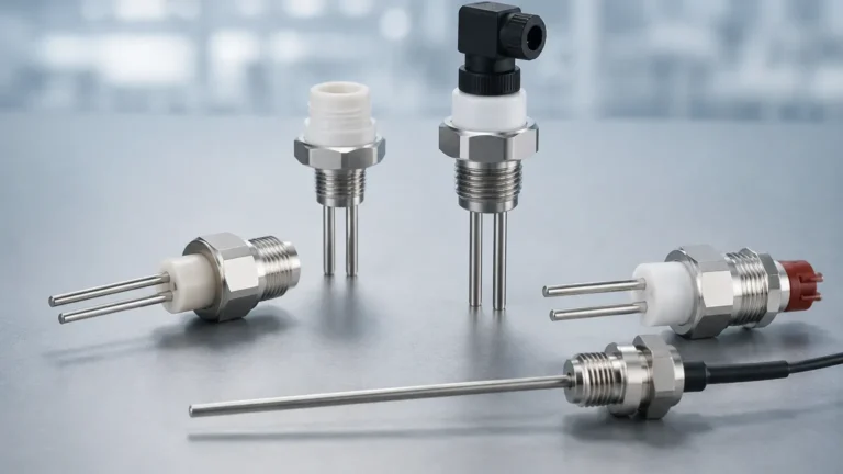
Vega Floor
Vega Floor
In the field of industrial automation, the term "Vega floor" often pertains to the technical challenges and signal processing requirements associated with measuring liquid or solid levels near the bottom of a vessel. Whether dealing with radar signal penetration in low-dielectric media or managing the "dead zone" of an ultrasonic sensor, understanding how a level meter interacts with the tank floor is critical for process safety and inventory accuracy. This guide explores the principles of level measurement near the vessel bottom, selection criteria for different technologies, and practical installation strategies for industrial applications.
Understanding Level Measurement Principles
Before selecting a sensor to manage "floor" level detection, it is essential to understand the underlying physics of the primary measurement technologies used in modern industry.
Radar Level Measurement (ToF)
Radar level meters, such as those produced by Welk, utilize Time-of-Flight (ToF) technology. The sensor emits high-frequency microwave pulses (typically in the 26 GHz or 80 GHz range). These pulses travel at the speed of light, reflect off the surface of the medium, and return to the sensor. The distance is calculated based on the time interval. When the level is near the vessel floor, the radar must distinguish between the reflection from the product surface and the reflection from the floor itself.
Ultrasonic Level Measurement
Ultrasonic sensors emit mechanical sound waves. These waves require a medium (usually air) to travel. They reflect off the surface and return to the transducer. Ultrasonic technology is cost-effective but is sensitive to temperature fluctuations, heavy foam, and vacuum conditions. Near the floor, ultrasonic sensors are limited by their "blocking distance," a zone directly beneath the sensor where measurement is impossible.
Hydrostatic Pressure Measurement
Hydrostatic transmitters measure the pressure exerted by a liquid column. The pressure at the bottom of the tank is directly proportional to the height of the liquid and its density ($P = \rho \cdot g \cdot h$). This method is highly effective for floor-level measurements because it does not rely on signal reflections; however, it requires contact with the medium and is density-dependent.
The Concept of "Floor Echo" in Industrial Radar
In radar applications, the "floor" is not just a physical boundary; it is a potential source of signal interference. This is particularly relevant when measuring liquids with a low dielectric constant ($\\epsilon_r < 3$), such as oils or hydrocarbons.
When the dielectric constant is low, a portion of the radar signal penetrates the liquid surface, travels through the medium, reflects off the metal tank floor, and returns to the sensor. This creates a "floor echo." If the sensor's software is not configured to handle this, it may jump between the actual liquid level and the floor reflection, leading to erratic readings. Advanced radar systems use "Floor Echo Tracking" or "False Echo Suppression" to map the tank bottom when empty, allowing the processor to ignore the floor signal and focus on the true surface reflection.
For engineers looking to implement these advanced tracking features, reviewing the Main Page of specialized manufacturers like Welk can provide insights into how modern signal processing algorithms handle low-level detection in complex geometries.
Selection Criteria for Level Measurement Near the Tank Floor
Choosing the right instrument depends on the physical properties of the medium and the physical constraints of the vessel. Use the following table to evaluate the suitability of different technologies for floor-proximate measurements.
Technology Comparison Table
| Feature | Radar (80 GHz) | Ultrasonic | Hydrostatic | Magnetic Level Gauge |
| :— | :— | :— | :— | :— |
| Minimum Measurable Level | 5 mm – 10 mm | 100 mm – 500 mm | 0 mm (at diaphragm) | 50 mm (float dependent) |
| Accuracy | ±1 mm to ±2 mm | ±0.25% of range | ±0.1% to ±0.5% | ±5 mm to ±10 mm |
| Effect of Low Dielectric | High (Floor echo risk) | None | None | None |
| Dead Zone | Minimal (approx. 50 mm) | Significant | None | Significant (bottom of chamber) |
| Cost | Higher | Moderate | Low to Moderate | Moderate |
| Maintenance | Low (Non-contact) | Low (Non-contact) | Moderate (Contact) | Moderate (Moving parts) |
Key Evaluation Factors
1. Dielectric Constant ($\\epsilon_r$): If the liquid is non-conductive (e.g., diesel, plastic pellets), radar signals will likely hit the floor. Hydrostatic or Guided Wave Radar (GWR) may be more reliable.
2. Vessel Bottom Shape: Conical or dished bottoms focus reflections differently than flat floors. A flat floor provides a strong, direct reflection that can easily be mistaken for a level signal.
3. Agitators and Obstructions: If there are cooling coils or agitator blades near the floor, non-contact sensors must have a narrow beam angle (like 80 GHz radar) to avoid false triggers.
Installation and Calibration Considerations
To ensure the sensor accurately tracks the level down to the "vega floor" or tank bottom, specific installation protocols must be followed.
Managing the Dead Zone
Every non-contact sensor has a dead zone (blocking distance). For an ultrasonic sensor, this might be 250 mm. If the sensor is mounted too close to the maximum fill level, it will lose the signal. Conversely, if the goal is to measure the very bottom of the tank, the sensor must be calibrated so that its 4mA (or 0%) point corresponds exactly to the floor.
False Echo Mapping
Before the tank is put into service, a "mapping" run should be performed. With the tank empty, the sensor scans the entire height. It records the reflection from the floor and any internal struts. This data is stored as a "static map." During operation, the sensor subtracts this map from the live signal, ensuring that the floor reflection is never mistaken for the product level.
Mounting Position
* Avoid the Center: In cylindrical tanks with flat floors, mounting the sensor in the exact center can create a "parabolic effect," where the floor reflection is amplified, causing signal saturation.
* Nozzle Height: Ensure the mounting nozzle is short enough that it does not interfere with the signal beam. For radar, a nozzle height-to-diameter ratio of 1:1 is generally preferred.
* Stilling Wells: In cases of extreme turbulence or very low dielectric constants, installing the sensor inside a stilling well (a bypass pipe) can eliminate floor echo issues by providing a consistent, concentrated reflection surface.
Limitations and Common Risks
While modern instrumentation is highly capable, there are inherent limitations when measuring at the floor level:
1. Sediment and Buildup: In wastewater or chemical processing, sludge can accumulate on the floor. This changes the reflection properties and can coat hydrostatic diaphragms, leading to "zero shift" or measurement drift.
2. Vapor and Condensation: While radar is largely unaffected by vapor, ultrasonic sensors can fail if heavy condensation forms on the transducer face, which often happens in closed tanks near the floor where humidity is trapped.
3. Minimum Detectable Level: No sensor can measure absolute zero. There is always a physical or electronic limit (typically 5 mm to 50 mm) where the signal becomes indistinguishable from the background noise of the floor.
4. Multi-Phase Liquids: If there is a layer of water beneath an oil layer (interface measurement), the sensor must be specifically calibrated to detect the interface rather than the floor.
Frequently Asked Questions (FAQ)
Q: Can a radar sensor measure right down to the metal floor?
A: Yes, but only if the medium has a high dielectric constant (like water). If the medium is an oil, the radar may "see through" the liquid to the floor. In such cases, the software must be used to distinguish the surface from the floor reflection.
Q: What is the best technology for measuring the floor level of a dry silo?
A: For solids, high-frequency (80 GHz) radar is preferred because it can penetrate dust and has a narrow beam that avoids hitting the silo walls. However, the angle of repose of the material at the floor must be considered.
Q: How does temperature affect floor-level readings?
A: Temperature primarily affects ultrasonic sensors by changing the speed of sound. Hydrostatic sensors may also experience drift if the liquid density changes significantly with temperature. Radar is the most stable across wide temperature ranges.
Q: Why does my sensor show a "Full" reading when the tank is actually at the floor level?
A: This is usually caused by a "double reflection" or a "ringing" effect where the signal bounces between the floor and the tank roof. Proper false echo mapping usually resolves this.
Conclusion
Achieving accurate measurement at the "vega floor" or vessel bottom requires a combination of the right technology and precise calibration. While radar offers the most versatility for non-contact applications, hydrostatic and ultrasonic options remain viable for specific process conditions. By understanding the dielectric properties of the medium and the geometric constraints of the vessel, engineers can implement reliable level control systems that minimize the risk of dry-run pumps or inaccurate inventory data. For further technical specifications and to explore a wide range of industrial level measurement instruments, users are encouraged to visit the Main Page for professional guidance and product selection support.