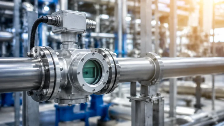
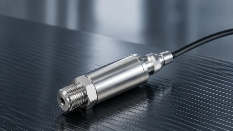
Vortex Flowmeters
Vortex Flowmeters
In the landscape of industrial process control, the accurate measurement of fluid movement is as critical as the monitoring of tank inventories. Vortex flowmeters have emerged as one of the most versatile and reliable tools for measuring the flow rate of liquids, gases, and steam. Known for their lack of moving parts and high durability, these instruments are staples in power generation, chemical processing, and water management. This guide provides a comprehensive technical overview of vortex flowmeter technology, its selection criteria, and its integration into broader industrial systems alongside level measurement solutions.
Understanding the Measurement Principle: The Von Kármán Effect
Before selecting a flowmeter, it is essential to understand the physical phenomenon that governs its operation. Vortex flowmeters operate based on the Von Kármán effect, a principle of fluid dynamics first theorized by Theodore von Kármán in the early 20th century.
The Mechanism of Vortex Shedding
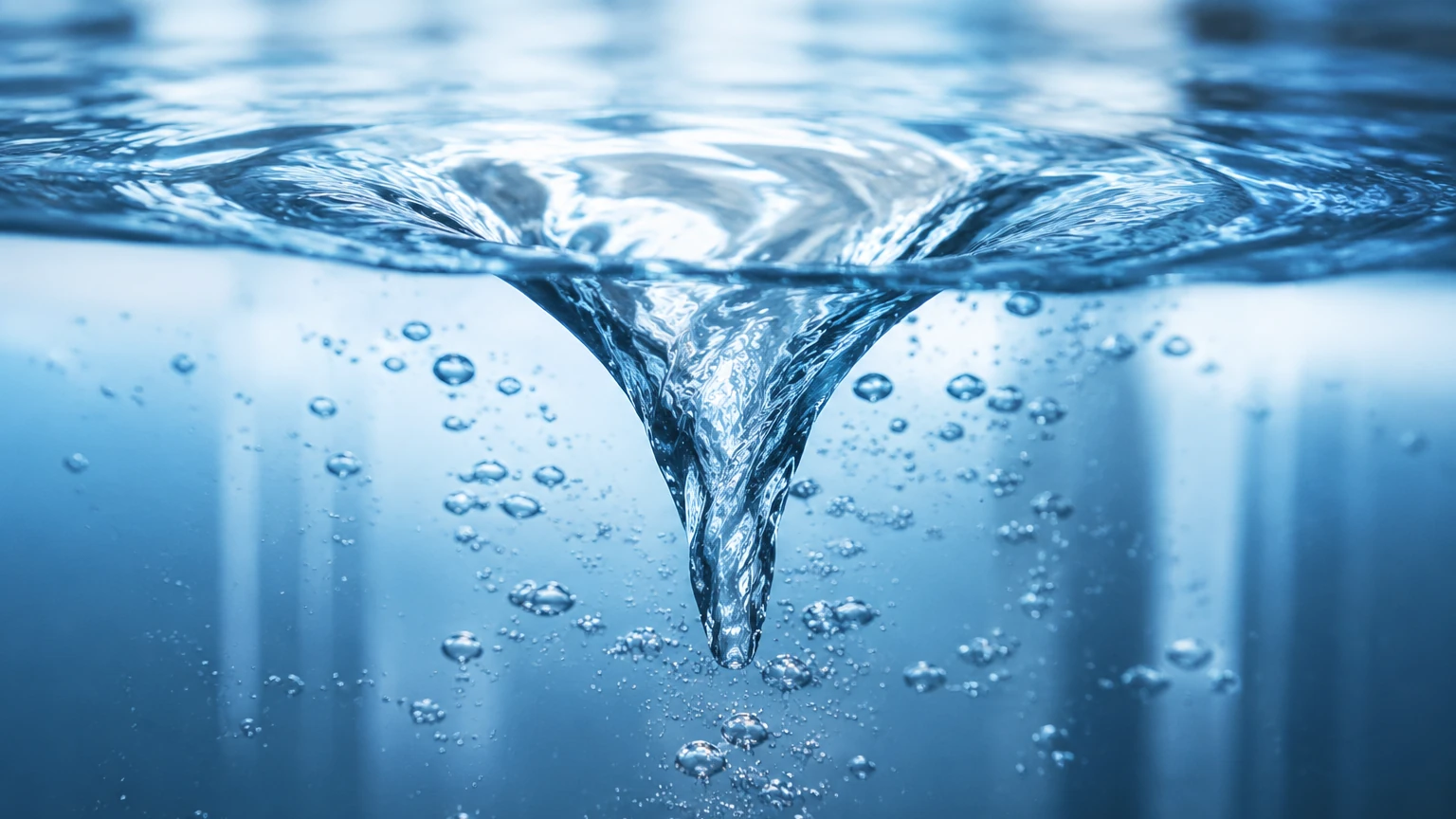
When a fluid (liquid, gas, or steam) flows past a non-streamlined object, known as a "bluff body" or "shedder bar," it cannot follow the sharp contours of the object. This causes the fluid layers to separate and roll into alternating vortices—swirling eddies—on downstream sides of the body.
These vortices are shed in a staggered, periodic pattern. The frequency at which these vortices are shed is directly proportional to the velocity of the fluid. The relationship is defined by the Strouhal number ($St$), a dimensionless parameter that remains constant over a wide range of Reynolds numbers. The formula is expressed as:
$$f = \frac{St \cdot v}{d}$$
Where:
- $f$ is the vortex shedding frequency.
- $St$ is the Strouhal number.
- $v$ is the flow velocity.
- $d$ is the width of the bluff body.
By measuring the frequency of these pressure fluctuations using piezoelectric sensors or ultrasonic detectors, the instrument calculates the flow velocity. When combined with the cross-sectional area of the pipe, the volumetric flow rate is determined. Because the shedding frequency depends only on the geometry of the bluff body and the velocity of the fluid, the measurement is relatively independent of fluid density, viscosity, pressure, and temperature, provided the flow remains turbulent.
Key Components and Construction
A standard vortex flowmeter consists of three primary components designed to withstand harsh industrial environments:
1. The Meter Body: Usually constructed from stainless steel (e.g., 316SS) or high-nickel alloys like Hastelloy for corrosive applications. It houses the flow passage and the bluff body.
2. The Shedder Bar (Bluff Body): A precisely machined vertical bar placed across the flow stream. Its shape (often triangular or trapezoidal) is optimized to generate strong, detectable vortices.
3. The Sensor Assembly: Located downstream or integrated into the shedder bar, this sensor detects the micro-pressure changes caused by the vortices. Most modern units use piezoelectric crystals that convert mechanical stress into electrical signals.
4. The Transmitter: This electronic component processes the raw frequency signal, applies temperature or pressure compensation (in multivariable models), and outputs a standard signal such as 4-20 mA, HART, or Modbus.
Evaluation Criteria for Industrial Applications
When evaluating vortex flowmeters for a specific project, engineers must consider several technical parameters to ensure long-term accuracy and reliability.
Fluid Phase and Compatibility
Vortex meters are "all-purpose" in that they can handle liquids, gases, and steam. However, the fluid must be clean. Suspended solids or high-viscosity liquids (typically above 10-30 centipoise) can dampen the vortex formation or clog the sensor area, leading to inaccurate readings.
Reynolds Number Requirements
For a vortex flowmeter to maintain its linear accuracy, the flow must be sufficiently turbulent. This is measured by the Reynolds number ($Re$). Most industrial vortex meters require a minimum $Re$ of approximately 10,000 to 20,000. If the flow rate drops too low (laminar flow), the vortices stop shedding, and the meter will read zero. This "low-flow cutoff" is a critical consideration in systems with high turndown requirements.
Process Conditions
* Temperature: Standard models handle up to 250°C, while specialized high-temperature versions can reach 400°C, making them ideal for superheated steam.
* Pressure: Depending on the flange rating (e.g., DIN PN40 or ANSI 300#), these meters can operate in high-pressure environments common in oil and gas midstream applications.
Selection Table: Vortex vs. Alternative Flow Technologies
Choosing the right technology requires a comparison of performance characteristics. The following table compares vortex flowmeters with other common industrial flow measurement methods.
| Feature | Vortex Flowmeter | Electromagnetic (Mag) | Ultrasonic (Transit-Time) | Differential Pressure (DP) |
| :— | :— | :— | :— | :— |
| Fluid Type | Liquid, Gas, Steam | Conductive Liquids | Clean Liquids/Gases | Liquid, Gas, Steam |
| Moving Parts | None | None | None | None (Primary element) |
| Accuracy | ±0.75% to ±1.0% | ±0.5% | ±0.5% to ±2.0% | ±1.0% to ±3.0% |
| Turndown Ratio | 10:1 to 30:1 | 100:1 | 50:1 | 4:1 to 10:1 |
| Pressure Drop | Moderate | Negligible | Negligible | High |
| Maintenance | Low | Low | Low | Medium (Impulse lines) |
| Primary Use Case | Steam & Gas utility | Water & Slurry | Large pipes/Retrofits | High-pressure steam |
Installation Best Practices and Pipe Requirements
The performance of a vortex flowmeter is highly dependent on the velocity profile of the fluid entering the meter. Disturbed flow patterns caused by valves, elbows, or pumps can introduce significant errors.
Straight Pipe Runs
To ensure a fully developed turbulent flow profile, the following minimum straight-run requirements (expressed in pipe diameters, D) are generally recommended:
* Upstream: 10D to 20D depending on the upstream obstruction (e.g., a single elbow requires 10D, while a pressure regulator may require 40D).
* Downstream: 5D after the meter body.
If these distances cannot be met due to space constraints, flow straighteners or vane-type conditioners must be installed.
Orientation and Piping
* Horizontal Piping: The meter should be installed such that the pipe is always full. For liquid applications, the sensor should be oriented to avoid air pocket entrapment.
* Vertical Piping: Flow should ideally move upward to ensure the pipe remains full of liquid and to prevent sediment build-up around the shedder bar.
* Vibration: While modern digital signal processing (DSP) can filter out some noise, excessive pipe vibration can interfere with the piezoelectric sensor. Supporting the pipe on both sides of the meter is a standard engineering practice.
Operational Limitations and Common Risks
While robust, vortex flowmeters are not universal solutions. Engineers should be aware of the following limitations:
1. Cavitation: In liquid applications, if the local pressure drops below the vapor pressure of the liquid (often due to the pressure drop across the shedder bar), vapor bubbles form and collapse. This "cavitation" damages the sensor and causes erratic readings. Maintaining a backpressure of at least 1.3 times the vapor pressure is recommended.
2. Wet Steam: Vortex meters measure the velocity of the fluid. In saturated steam applications, if the steam quality drops (becoming "wet" with water droplets), the meter will only measure the velocity of the gas phase, leading to an underestimation of the total mass flow unless multivariable compensation is used.
3. Sensitivity to Noise: High-frequency mechanical noise from nearby machinery or hydraulic shock can occasionally be misinterpreted as vortex signals. Selecting a transmitter with advanced signal filtering is vital for noisy environments.
Integrating Flow and Level Measurement Systems
In many industrial processes, flow measurement and level measurement are two sides of the same coin. For instance, in boiler feedwater systems, a vortex flowmeter measures the steam output while a hydrostatic or radar level transmitter monitors the water level in the drum. Discrepancies between the flow out (steam) and the flow in (water), as reconciled by the level change, are used to detect leaks or inefficiencies.
For engineers designing integrated process loops, it is helpful to consult comprehensive resources. You can Review product options and application support at the Welk Main Page to see how various level instruments complement flow control strategies in chemical and water treatment sectors.
In tank inventory management, flowmeters provide the "rate of change" data, while level meters provide the "absolute volume" data. Using both allows for redundant verification and improved safety, particularly in preventing overfill conditions in high-pressure vessels.
Frequently Asked Questions (FAQs)
Q: Can vortex flowmeters measure low-velocity flows?
A: Generally, no. Vortex shedding requires a minimum velocity to generate detectable pressure pulses. If the velocity is too low (typically below 0.3 m/s for liquids or 3 m/s for gases), the meter will not provide a reading. For low-flow applications, differential pressure or thermal mass meters may be more appropriate.
Q: Do vortex flowmeters require periodic recalibration?
A: Because the shedding frequency is based on the physical geometry of the shedder bar, which does not change over time, vortex meters are extremely stable. Recalibration is usually only necessary if the shedder bar suffers from erosion or chemical corrosion that alters its shape.
Q: What is a multivariable vortex flowmeter?
A: A multivariable model includes a built-in temperature sensor (RTD) and sometimes a pressure transducer. This allows the transmitter to calculate the density of the fluid in real-time and provide a mass flow output (e.g., kg/h), which is particularly useful for steam and compressed air where density varies with process conditions.
Q: How does pipe scale affect the meter?
A: Significant buildup of scale or rust on the inside of the pipe or the shedder bar can change the effective diameter ($d$) and the Strouhal number, leading to measurement drift. In systems prone to scaling, periodic inspection of the meter internals is recommended.
Conclusion
Vortex flowmeters represent a mature, reliable technology for modern industrial flow measurement. By understanding the underlying physics of vortex shedding and adhering to strict installation guidelines regarding straight pipe runs and fluid conditions, operators can achieve high-precision monitoring of steam, gas, and liquid flows. When integrated with high-quality level measurement instruments, these devices form the backbone of efficient and safe industrial process control. For further technical specifications on level and flow integration, visiting the Main Page provides access to a wide range of industrial instrumentation solutions tailored for global automation needs.