Impeller Flow Meter
Impeller Flow Meter
In the landscape of industrial fluid handling, the impeller flow meter remains one of the most reliable and cost-effective solutions for measuring the velocity and volumetric flow rate of liquids. Often referred to interchangeably with paddlewheel meters or turbine meters depending on their specific rotor geometry, these instruments are foundational in sectors ranging from municipal water treatment to complex chemical processing. This guide provides a technical overview of impeller flow meter technology, selection criteria, and integration strategies within broader process automation frameworks.
Measurement Principles of Impeller Flow Meters
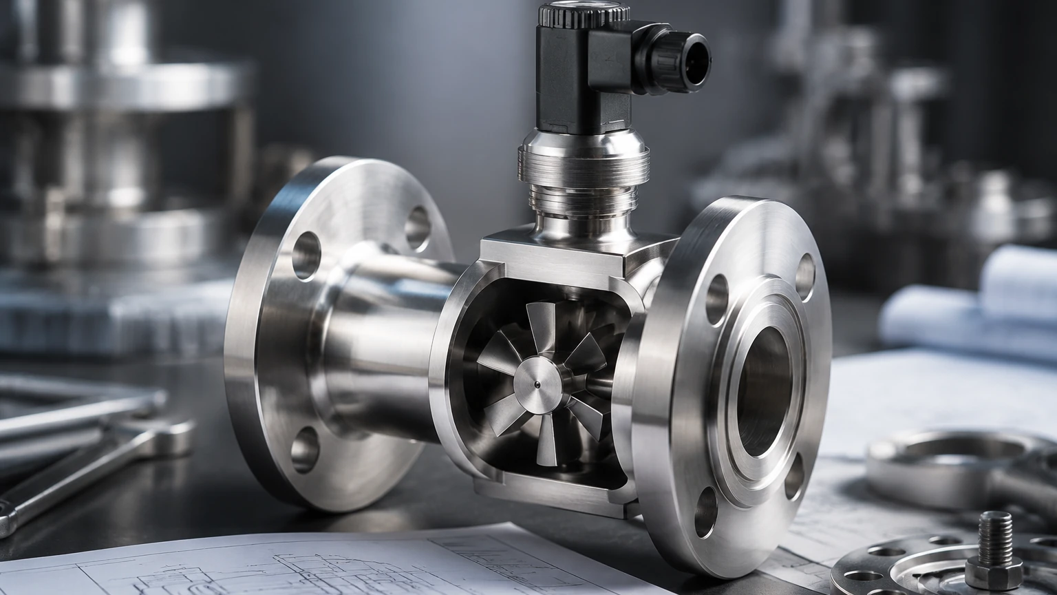
The operation of an impeller flow meter is rooted in the mechanical conversion of fluid kinetic energy into rotational motion. The core component is a multi-bladed rotor (the impeller) suspended in the fluid stream. As the liquid moves through the pipe, it impacts the blades, causing the rotor to spin.
The Relationship Between Velocity and Rotation
There is a direct, linear relationship between the velocity of the fluid and the angular velocity of the impeller. In a well-designed meter, the rotational speed is proportional to the flow rate over a wide range of Reynolds numbers. This relationship is defined by the meter’s "K-factor," which represents the number of pulses generated per unit volume of fluid (e.g., pulses per liter).
Signal Generation and Detection
To translate mechanical rotation into an electronic signal, most modern impeller flow meters utilize non-intrusive sensing technologies:
1. Hall Effect Sensors: A magnet is embedded in one or more of the impeller blades. As the blade passes a sensor located outside the fluid chamber, it triggers a voltage change, producing a square-wave pulse.
2. Inductive/Coil Sensors: The rotating blades disturb a magnetic field generated by a coil in the sensor head, inducing a low-voltage AC signal. This is common in high-temperature or high-purity applications where magnets might be undesirable.
3. Optical Sensors: In specific laboratory environments, infrared beams may be used to count blade passes, though this is rare in industrial settings due to potential fluid opacity.
The resulting frequency signal is then processed by a local transmitter or a remote PLC (Programmable Logic Controller) to display real-time flow rates (e.g., m³/h or L/min) and totalized flow.
Technical Selection Criteria
Choosing the correct impeller flow meter requires a detailed understanding of the process fluid and the hydraulic conditions of the system. Unlike non-intrusive methods like ultrasonic level sensors, the impeller is a wetted part, meaning material compatibility is paramount.
Material Compatibility
For water treatment, plastic bodies (PVC, Polypropylene, or PVDF) are standard. However, in chemical or high-pressure industrial automation environments, stainless steel (316L) or specialized alloys are required. The bearing material—often ceramic, ruby, or tungsten carbide—is the most critical wear point and must be chosen based on the lubricity and abrasiveness of the fluid.
Selection Comparison Table
The following table outlines the typical performance characteristics of various impeller flow meter configurations:
| Feature | Paddlewheel (Insertion) | Inline Turbine | High-Pressure Impeller |
| :— | :— | :— | :— |
| Typical Accuracy | ±1% to ±4% of Full Scale | ±0.25% to ±1% of Rate | ±1% to ±2% of Rate |
| Pipe Size Range | 15 mm to 900 mm | 6 mm to 300 mm | 10 mm to 100 mm |
| Max Pressure | 10–15 bar (145–217 psi) | Up to 250 bar (3625 psi) | Up to 400 bar (5800 psi) |
| Viscosity Limit | Low (< 5 cSt) | Low to Medium (< 100 cSt) | Low (< 10 cSt) |
| Primary Use Case | Large pipe water monitoring | High-precision dosing | Hydraulic oil monitoring |
Installation Considerations and Best Practices
The accuracy of an impeller flow meter is heavily dependent on the flow profile of the fluid as it enters the meter. Turbulence caused by elbows, valves, or pumps can lead to significant measurement errors.
Straight Pipe Requirements
To ensure a laminar or fully developed turbulent flow profile, engineers must adhere to the "10D/5D" rule. This requires a straight run of pipe equal to at least 10 times the pipe diameter (D) upstream of the meter and 5 times the diameter downstream. If the upstream piping includes complex configurations like double elbows or partially closed valves, the upstream requirement may increase to 20D or 40D.
Orientation and Air Pockets
* Horizontal Pipes: The meter should ideally be installed at the 3 o'clock or 9 o'clock position on the pipe circumference. This prevents air bubbles (which collect at the top) and sediment (which settles at the bottom) from interfering with the impeller rotation.
* Vertical Pipes: Flow should always be in an upward direction. This ensures the pipe remains completely full of liquid and prevents the "waterfall effect" that occurs in downward flows, which can cause the impeller to spin at erratic speeds.
Mechanical Clearances
For insertion-type meters, the depth of the impeller in the pipe is critical. Most manufacturers provide specific installation fittings (tees or weld-on saddles) that ensure the impeller sits at the precise point in the velocity profile (usually the outer 1/8th to 1/4th of the pipe diameter) to provide an accurate average velocity reading.
Limitations and Operational Constraints
While highly versatile, the impeller flow meter is not a universal solution. Engineers must be aware of several limiting factors:
1. Fluid Cleanliness: Because the impeller relies on mechanical bearings, fluids containing large solids, fibrous materials, or high concentrations of abrasives can cause the rotor to jam or wear prematurely. Strainers are often recommended upstream.
2. Viscosity Sensitivity: As fluid viscosity increases, the drag on the impeller changes, shifting the K-factor. These meters are generally best suited for water-like liquids. For high-viscosity oils or polymers, positive displacement or Coriolis meters are typically preferred.
3. Mechanical Wear: Moving parts inevitably wear out. In continuous 24/7 operations, the impeller and bearings may require replacement every 12 to 24 months depending on the fluid's lubricity.
4. Pressure Drop: Although minimal compared to orifice plates, the impeller does introduce a slight pressure drop into the system, which must be accounted for in low-pressure gravity-fed applications.
Integration with Level Measurement Systems
In many industrial applications, flow measurement is only one half of the equation. For example, in chemical tank farm management or municipal reservoir control, flow data from an impeller flow meter is used in conjunction with level data to verify system integrity.
If a radar level meter shows a decreasing tank level but the downstream flow meter shows no movement, this discrepancy immediately alerts operators to a potential leak or a blockage. Welk provides a comprehensive suite of industrial level measurement instruments, including radar and ultrasonic sensors, that work alongside flow instrumentation to provide a complete picture of process dynamics. For engineers looking to optimize their entire measurement loop, you can Review product options and application support on our Main Page to see how these technologies integrate.
Maintenance and Troubleshooting
Regular maintenance ensures the longevity of the impeller flow meter. A standard maintenance schedule should include:
* Visual Inspection: Checking for signs of leakage around the sensor housing or mounting fitting.
* Bearing Check: Removing the sensor to ensure the impeller spins freely and quietly. Any "grittiness" in the rotation indicates bearing wear or debris buildup.
* Cleaning: Removing scale or calcium deposits in hard-water applications using a mild descaling agent.
Common Troubleshooting Steps
| Symptom | Potential Cause | Solution |
| :— | :— | :— |
| No signal output | Impeller jammed or sensor failed | Inspect for debris; test sensor with a magnet |
| Inaccurate high reading | Air bubbles in the line | Check for pump cavitation or pipe leaks |
| Inaccurate low reading | Partial blockage or worn bearings | Clean the impeller; replace the rotor assembly |
| Erratic signal | Electrical interference | Ensure shielded cabling is used and grounded |
Frequently Asked Questions (FAQ)
Q: Can an impeller flow meter measure gas flow?
A: Generally, no. Standard impeller meters are designed for the density and momentum of liquids. Measuring gases requires specialized high-speed turbine meters or thermal mass flow sensors.
Q: How often should I recalibrate my impeller flow meter?
A: For most industrial applications, an annual calibration check is sufficient. However, if the fluid is mildly abrasive or the meter is used for fiscal billing (custody transfer), semi-annual calibration may be required.
Q: What is the minimum flow velocity required?
A: Most impeller meters require a minimum velocity of approximately 0.3 m/s (1 fps) to overcome the initial friction of the bearings. Below this threshold, the meter may not spin or may provide highly non-linear results.
Q: Are these meters suitable for sanitary applications?
A: Yes, there are specific "tri-clamp" or hygienic versions of impeller flow meters made from FDA-approved materials, though they must be designed to eliminate "dead spaces" where bacteria could grow.
Conclusion
The impeller flow meter remains a staple of B2B industrial instrumentation due to its balance of performance and cost. By understanding the mechanical principles and adhering to strict installation guidelines, process engineers can achieve reliable flow data for years. When combined with advanced level measurement technologies—such as hydrostatic transmitters or magnetic level gauges—these meters form the backbone of efficient industrial automation and resource management. For detailed technical specifications on complementary level sensing equipment, visiting the Main Page provides access to a wider range of industrial solutions tailored for water treatment, oil and gas, and chemical processing.