Flow Calibration Services
Flow Calibration Services
In the landscape of industrial automation and process control, the precision of measurement instruments is the foundation of operational efficiency and safety. Flow calibration services provide the necessary verification and adjustment of flow meters to ensure that their output accurately reflects the actual volume or mass of fluid passing through a system. For industries ranging from water treatment to chemical processing, maintaining the integrity of these measurements is not merely a maintenance task but a critical regulatory and economic requirement.
Flow calibration involves comparing the performance of a flow meter under test against a reference standard of higher accuracy. This process identifies the degree of error and allows for the adjustment of the instrument or the application of correction factors. As a professional manufacturer like Welk provides advanced level and flow measurement solutions, understanding the nuances of how these devices are calibrated ensures long-term reliability in the field.
Measurement Principles and Calibration Logic
Before selecting flow calibration services, it is essential to understand the underlying principles of the instruments being serviced. Flow measurement is generally categorized into closed-pipe systems and open-channel systems, each requiring distinct calibration approaches.
Velocity and Area Principles
In closed pipes, flow is often calculated by measuring the velocity of the fluid and multiplying it by the cross-sectional area of the pipe ($Q = A \times v$). Instruments such as ultrasonic flow meters use transit-time or Doppler shift principles to determine velocity. Calibration for these devices focuses on verifying the timing electronics and the transducer's ability to detect signal shifts accurately.
Level-to-Flow Conversion (Open Channels)
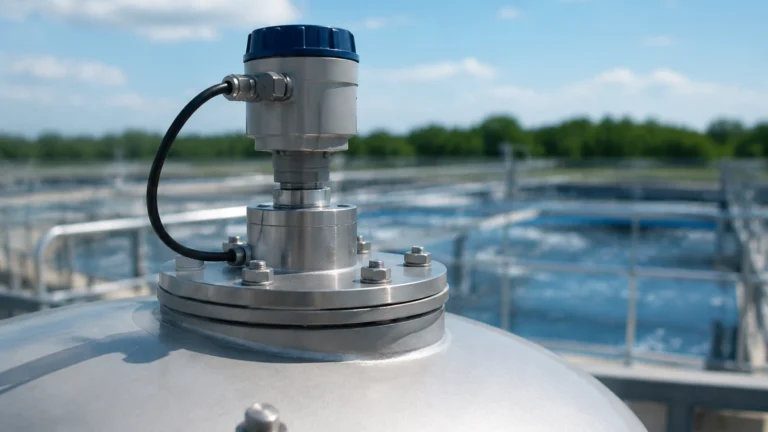
In water treatment and irrigation, flow is frequently measured in open channels using flumes or weirs. Here, the flow rate is a function of the liquid level (head) upstream of the structure. Level measurement instruments, such as radar level meters or ultrasonic level sensors, are used to detect this height. Calibration in this context involves two steps: ensuring the level sensor accurately measures the distance to the liquid surface and verifying that the conversion formula (e.g., the Manning equation or specific weir curves) correctly translates that level into a flow rate.
Hydrostatic and Differential Pressure
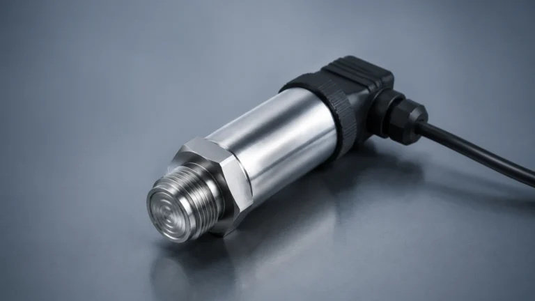
Hydrostatic level transmitters measure the pressure exerted by a liquid column to determine height. In flow applications, differential pressure (DP) meters measure the pressure drop across an orifice plate or Venturi tube. Calibrating these systems requires precise pressure generators and deadweight testers to ensure the sensor responds linearly to changes in force.
Primary Methods of Flow Calibration Services
Professional flow calibration services typically employ one of three primary methodologies to establish a traceable reference standard.
1. Gravimetric Calibration
This is widely considered the most accurate method. It involves weighing the amount of fluid that passes through the meter over a specific period. By using high-precision scales and NIST-traceable weights, the mass flow is determined. If volumetric flow is required, the fluid's density must be precisely known, often requiring temperature compensation. This method is common in laboratory settings for high-accuracy master meters.
2. Master Meter Calibration
In this method, the meter under test is placed in series with a "master meter"—an instrument that has been recently calibrated to a primary standard and possesses a known, high degree of accuracy. The readings from both meters are compared across various flow rates. This is a common technique for field calibration because it is more portable than gravimetric systems.
3. Piston Prover (Volumetric) Method
A piston prover uses a high-precision bore and a moving piston to displace a known volume of fluid through the meter. By measuring the time it takes for the piston to travel a specific distance, the flow rate is calculated. This method is excellent for low flow rates and high-viscosity fluids where other methods might struggle with turbulence or aeration.
Selection Criteria for Calibration Methods
Choosing the right calibration approach depends on the instrument type, the required accuracy, and the operational environment. The following table provides a comparison of common methods used by flow calibration services.
| Method | Typical Accuracy | Best For | Limitations |
| :— | :— | :— | :— |
| Gravimetric | ±0.01% to ±0.1% | Primary standards, high-precision lab work | Expensive, time-consuming, requires stable density |
| Master Meter | ±0.2% to ±0.5% | Field verification, routine maintenance | Accuracy is dependent on the master meter's state |
| Piston Prover | ±0.05% to ±0.2% | Low flow rates, specialized chemicals | Limited volume capacity per stroke |
| Transfer Standard | ±0.5% to ±1.0% | Large diameter pipes, site check-ups | Higher uncertainty than lab methods |
Installation Considerations for Calibrated Instruments
Even a perfectly calibrated meter will provide inaccurate data if installed incorrectly. When returning an instrument to service after utilizing flow calibration services, the following engineering guidelines must be observed:
* Straight Pipe Runs: Most flow meters require a specific length of straight pipe upstream and downstream to eliminate turbulence. A common rule of thumb is 10 diameters (10D) of straight pipe upstream and 5 diameters (5D) downstream. For example, a 100 mm (4 in) pipe requires 1000 mm (40 in) of straight run before the meter.
* Orientation and Leveling: For level-based flow systems, such as those using radar or ultrasonic sensors over a flume, the sensor must be mounted perfectly perpendicular to the liquid surface. A tilt of even a few degrees can result in significant measurement errors.
* Full Pipe Requirement: Electromagnetic and ultrasonic meters usually require the pipe to be completely full. If the pipe is partially empty, the velocity-area calculation will fail. Installing the meter at a low point in the piping (a "U" section) can ensure it remains submerged.
* Environmental Shielding: Sensors should be protected from direct sunlight (which can cause thermal expansion or affect ultrasonic sound speed) and heavy wind, which can disturb the surface of the liquid in open-channel applications.

Common Risks and Limitations
While flow calibration services are essential, they are not a silver bullet. Engineers must be aware of the following risks:
1. Fluid Property Mismatch: If a meter is calibrated using water in a lab but used to measure a high-viscosity oil or a corrosive chemical in the field, the Reynolds number will differ, leading to measurement drift. Always confirm that the calibration fluid closely matches the process fluid.
2. Installation Effects: As noted above, the "as-installed" accuracy often differs from the "as-calibrated" accuracy due to piping configurations that were not present in the calibration rig.
3. Sensor Fouling: In wastewater or chemical applications, the buildup of scale or debris on the sensor face (for ultrasonic/radar) or the inner walls (for electromagnetic) will change the cross-sectional area or signal strength, rendering the calibration void over time.
4. Signal Interference: For electronic meters, electromagnetic interference (EMI) from nearby variable frequency drives (VFDs) or high-voltage lines can introduce noise into the signal, mimicking flow where none exists.
For those seeking to upgrade their hardware to more resilient technologies that simplify these challenges, you can Review product options and application support to find instruments designed for high-stability performance.
Frequently Asked Questions (FAQs)
Q: How often should I perform flow calibration?
A: Most industrial standards recommend annual calibration. However, if the process is highly corrosive or involves critical custody transfer, semi-annual or quarterly checks may be necessary. Always consult the manufacturer's guidelines for your specific model.
Q: What is the difference between calibration and validation?
A: Calibration is the act of comparing a device to a standard and adjusting it. Validation (or verification) is the process of checking the device against a standard to ensure it is still within its specified accuracy limits without necessarily making adjustments.
Q: Can I calibrate an ultrasonic level sensor for flow on-site?
A: Yes, this is often called a "dry calibration." You verify the distance measurement against a known physical reference (like a tape measure) and then program the flow curve into the transmitter. However, a "wet test" with actual fluid is always more accurate for verifying the total system.
Q: What is ISO 17025, and why does it matter for flow calibration services?
A: ISO 17025 is the international standard for the competence of testing and calibration laboratories. Using a service provider with this accreditation ensures that their equipment is traceable to national standards and that their processes are rigorously audited.
Summary of Best Practices
To maximize the value of flow calibration services, project managers should maintain detailed records of every instrument's calibration history. This data allows for trend analysis, helping to predict when an instrument is nearing the end of its functional life or when a process change is causing premature wear. When selecting new instrumentation, such as those found on the Welk Main Page, prioritize devices with built-in diagnostics that can alert operators to signal degradation before it impacts the accuracy of the flow data.
By combining high-quality measurement hardware with a rigorous calibration schedule, industrial facilities can ensure compliance, reduce waste, and optimize their process outputs with confidence.