Radar Level Transmitter Market
Radar Level Transmitter Market: An Engineering Guide to Selection and Application
In the landscape of industrial automation, the demand for precise, non-contact measurement has positioned radar technology as a cornerstone of process control. The radar level transmitter market has evolved from specialized, high-cost niche applications to a broad industrial standard, driven by the need for reliability in challenging environments. For engineers and procurement professionals, understanding the underlying physics and market trends is essential for selecting instrumentation that ensures both safety and operational efficiency.
Industrial Radar Level Meters utilize electromagnetic waves to determine the distance to a liquid or solid surface. Unlike ultrasonic sensors, which rely on sound waves and are susceptible to air temperature and pressure changes, radar signals travel at the speed of light and remain largely unaffected by the vapor space composition. This characteristic makes them ideal for the volatile environments found in the chemical, oil and gas, and water treatment sectors.
Measurement Principles: Pulse, FMCW, and Guided Wave
Before evaluating the radar level transmitter market for specific hardware, it is necessary to distinguish between the three primary measurement methodologies used in modern instrumentation.
1. Pulse Radar (Non-Contact)
Pulse radar, often operating in the 6GHz to 26GHz range, emits short microwave pulses toward the material surface. The instrument measures the "Time of Flight" (ToF)—the interval between the emission of the pulse and the reception of its echo. Because the speed of light is constant, the distance is calculated as:
*Distance = (Speed of Light × ToF) / 2*
2. Frequency Modulated Continuous Wave (FMCW)
FMCW is the current technological benchmark for high-accuracy applications. Instead of pulses, the transmitter emits a continuous signal with a constantly changing frequency. The reflection from the product surface is compared against the emitted signal. The frequency difference (the "beat frequency") is directly proportional to the distance. This method provides superior signal-to-noise ratios and is the standard for 80GHz high-frequency sensors.
3. Guided Wave Radar (GWR)
GWR is a contact-based technology. A microwave pulse is sent down a physical probe (cable or rod). When the pulse hits a medium with a different dielectric constant, a portion of the energy is reflected back. GWR is particularly effective in low-dielectric liquids, foaming surfaces, and applications with heavy internal tank obstructions where a free-to-air signal might be blocked.
Technical Selection Criteria
Choosing the correct instrument requires a detailed analysis of the process media and the vessel geometry. The following table provides a comparison of common radar configurations found in the current radar level transmitter market.
| Feature | 26GHz Pulse Radar | 80GHz FMCW Radar | Guided Wave Radar (GWR) |
| :— | :— | :— | :— |
| Measurement Type | Non-contact | Non-contact | Contact (Probe-based) |
| Beam Angle | Wide (approx. 10°–20°) | Narrow (approx. 3°–8°) | N/A (Signal follows probe) |
| Accuracy | ±3 mm to ±5 mm | ±1 mm | ±2 mm |
| Max Range | Up to 30 meters | Up to 120 meters | Up to 75 meters |
| Suitability | Large tanks, simple liquids | Small nozzles, solids, turbulence | Low dielectric, foam, bypass pipes |
| Dielectric Min ($ε_r$) | > 1.9 | > 1.4 | > 1.2 |
The Role of Dielectric Constant ($ε_r$)
The dielectric constant of the material is the most critical factor in radar selection. It determines how much energy is reflected. Water has a high dielectric (~80) and is easy to measure. Hydrocarbons often have low dielectrics (1.9 to 2.5), requiring more sensitive electronics or the use of Guided Wave Radar to concentrate the signal energy.
Market Trends: The Shift to 80GHz Technology
A significant trend in the radar level transmitter market is the rapid adoption of 80GHz high-frequency technology. The shorter wavelength allows for significantly smaller antenna sizes and narrower beam angles.
* Narrower Beams: An 80GHz transmitter can achieve a beam angle as narrow as 3°. This allows the signal to avoid internal tank obstructions such as ladders, agitators, and heating coils, which would cause "false echoes" in lower-frequency units.
* Better Resolution: Higher frequency allows for better separation between the actual product level and the bottom of the tank, reducing the "dead zone" at the lower end of the measurement range.
* Small Nozzle Compatibility: Because the antenna is smaller, 80GHz units can be installed on 1-inch or 2-inch nozzles, whereas 26GHz units often require 3-inch or 4-inch openings to maintain signal integrity.
Installation Considerations and Constraints
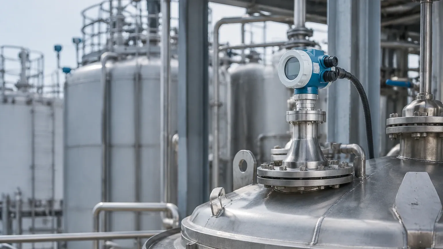
Even the most advanced radar level meters will fail if installation guidelines are ignored. Engineers must account for the physical environment of the vessel.
1. Nozzle Positioning: The transmitter should not be mounted in the center of a domed tank, as this can concentrate multiple reflections (parabolic effect) and confuse the sensor. Ideally, mount the unit at 1/6th of the tank diameter from the wall.
2. Obstruction Avoidance: The signal beam should have a clear path to the surface. If an agitator is present, the software must be configured with a "False Echo Suppression" or "Empty Tank Mapping" to ignore the static reflections from the blades.
3. Nozzle Height: The antenna should typically extend slightly past the bottom of the mounting nozzle to prevent signal interference from the nozzle walls (ringing). If the nozzle is very long, a wave guide or a specialized antenna extension may be required.
4. Dead Zones (Blocking Distance): Every radar has a minimum distance near the antenna where measurement is not possible. For non-contact radar, this is usually 100mm to 300mm. Ensure the maximum fill level does not enter this zone.
Application Risks and Limitations
While radar is highly versatile, certain conditions present risks to measurement accuracy:
* Heavy Foam: Dense, thick foam can absorb the radar signal entirely, leading to a "loss of echo." In these cases, Guided Wave Radar or a bypass pipe configuration is preferred.
* Dust and Condensation: While radar penetrates dust better than ultrasonic sensors, extremely heavy dust (in grain silos or cement plants) can coat the antenna. Units with integrated air purging or PTFE lens covers are recommended for these environments.
* Extreme Temperatures: High-temperature applications (above 250°C) require specialized cooling fins or high-temperature ceramic seals to protect the electronics from process heat.
International Procurement: A Buyer’s Checklist
When navigating the radar level transmitter market for global projects, international buyers should confirm the following technical specifications with the manufacturer:
* Hazardous Area Certifications: Does the unit meet ATEX, IECEx, or UL standards for explosive atmospheres?
* Output Protocols: Is the standard 4-20mA HART sufficient, or is there a requirement for Modbus RTU, Profibus, or Foundation Fieldbus?
* Material Compatibility: Is the wetted part material (316L Stainless Steel, Hastelloy, PTFE coating) compatible with the chemical properties of the media?
* Process Connection: Confirm the flange standard (ANSI, DIN, JIS) and pressure rating (PN16, PN40, 150lb, 300lb).
* Calibration Reports: Request factory calibration certificates to ensure the unit meets the stated accuracy before installation.
Frequently Asked Questions (FAQ)
Q: Can radar measure through a plastic tank wall?
A: Yes. Non-contact radar can often measure through plastic or fiberglass tank tops without a process opening, provided the material is not conductive and the thickness is within the sensor's capability. This is common in chemical IBC (Intermediate Bulk Container) monitoring.
Q: How does turbulence affect radar measurement?
A: Surface turbulence (ripples or waves) scatters the radar signal, which can weaken the echo. However, modern signal processing algorithms can average these fluctuations to provide a stable level reading. For extreme turbulence, a stilling well or GWR is recommended.
Q: Is maintenance required for radar level meters?
A: Because non-contact radar has no moving parts, maintenance is minimal. The primary task is checking for buildup on the antenna in dirty applications. Many modern units feature self-diagnostics that alert the control room if the signal strength degrades.
Q: What is the difference between 2-wire and 4-wire radar?
A: 2-wire units are loop-powered, meaning the power and the 4-20mA signal share the same pair of wires. 4-wire units have separate power supplies and are typically used when high power is needed for heating elements or complex processing.
By understanding these technical boundaries and the current state of the radar level transmitter market, industrial operators can implement measurement solutions that reduce downtime and improve process safety. For specific hardware configurations and technical support, professionals often consult detailed product options to match the instrument to the unique constraints of their facility.