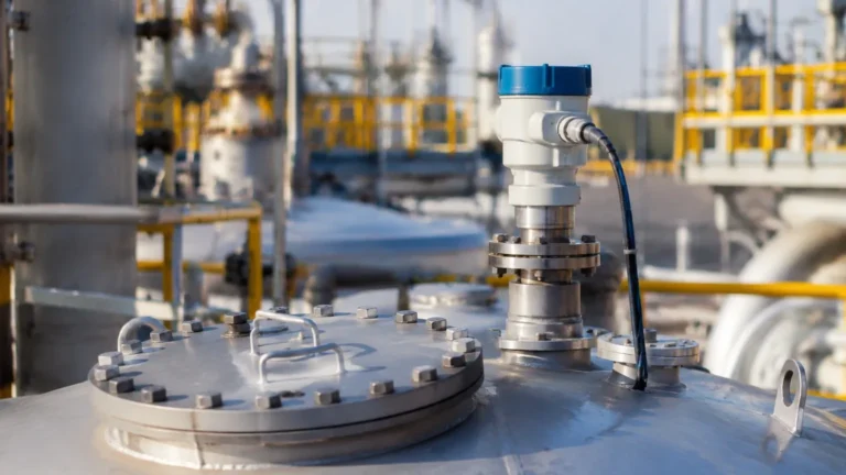
Radar Level Transmitter Magnetrol
Radar Level Transmitter Magnetrol: An Engineering Guide to High-Precision Measurement
In the landscape of industrial process control, accurate level measurement is fundamental to operational safety, inventory management, and process efficiency. Among the various technologies available, radar-based systems have emerged as the gold standard for challenging environments. Specifically, the radar level transmitter magnetrol series represents a significant segment of high-performance instrumentation used in oil and gas, chemical processing, and power generation.
This guide provides a technical overview of radar level measurement principles, compares guided wave versus non-contact technologies, and outlines the critical selection and installation criteria for engineers and procurement professionals looking to integrate Radar Level Meters into their infrastructure.
Understanding Radar Level Measurement Principles
Radar level transmitters operate on the principle of "Time of Flight" (ToF). The device emits electromagnetic pulses (microwaves) that travel at the speed of light. When these pulses encounter a medium with a different dielectric constant than the gas or vacuum they are traveling through, a portion of the energy is reflected back to the transmitter.
The Role of the Dielectric Constant (εr)
The dielectric constant of the process medium is the most critical factor in radar measurement. It determines how much signal energy is reflected.
- High Dielectric Media: Water-based liquids (εr > 30) reflect a strong signal, making them easy to measure.
- Low Dielectric Media: Hydrocarbons, oils, and certain solids (εr < 2.0) reflect very little energy.
Modern radar level transmitter magnetrol units utilize advanced signal processing and high-frequency electronics to detect these weak reflections, allowing for reliable measurement even in low-dielectric applications.
Pulse Radar vs. FMCW
There are two primary methods for measuring the time of flight:
1. Pulse Radar: The transmitter sends a short burst of microwave energy and measures the time it takes for the pulse to return. This is energy-efficient and suitable for many standard applications.
2. FMCW (Frequency Modulated Continuous Wave): The transmitter emits a continuous signal with a constantly changing frequency. The difference in frequency between the emitted and received signal is proportional to the distance. FMCW is generally preferred for high-accuracy requirements and complex tank geometries.
Comparing Guided Wave and Non-Contact Radar Technologies
When selecting a radar level transmitter magnetrol, engineers must choose between Guided Wave Radar (GWR) and Non-Contact Radar. Both utilize microwaves but deliver them to the process medium differently.
Guided Wave Radar (GWR)
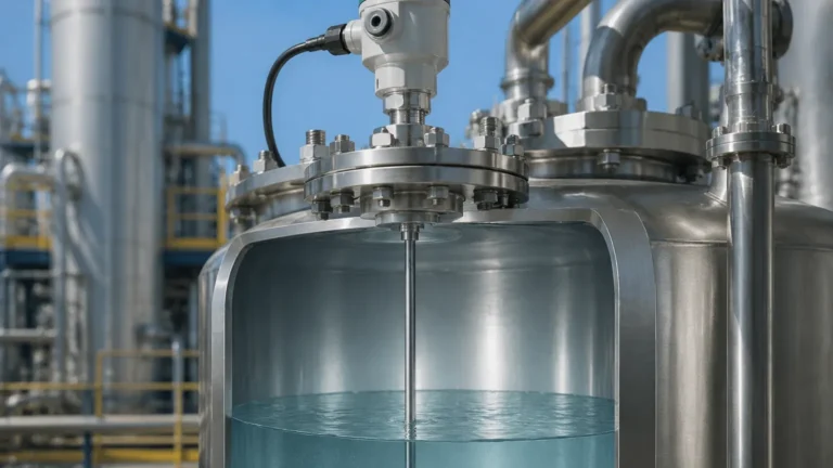
GWR transmitters use a physical probe (waveguide) to direct the microwave pulse from the electronics down to the liquid surface.
- Advantages: Since the signal is concentrated along the probe, it is less affected by foam, turbulence, or internal tank obstructions like agitators or baffles. It is highly effective for interface measurement (e.g., oil over water).
- Limitations: The probe must be in contact with the medium, which may not be suitable for highly corrosive or extremely viscous fluids that could coat the probe.
Non-Contact Radar
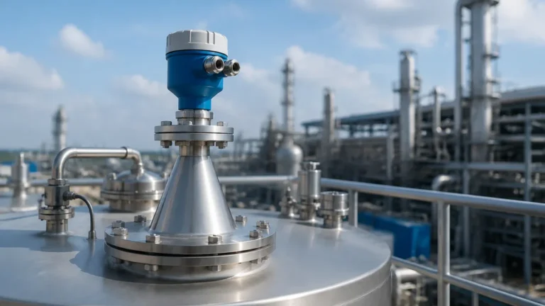
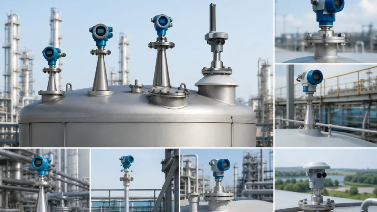
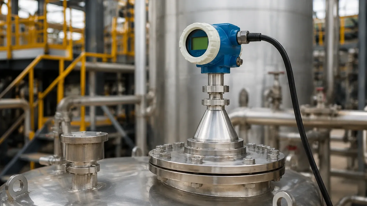
Non-contact radar level meters emit signals through an antenna (horn, rod, or drop antenna) and receive reflections from the surface without physical contact.
- Advantages: Ideal for corrosive, hygienic, or high-temperature applications where contact must be avoided. Maintenance is lower because there is no probe to clean or replace.
- Limitations: The signal spreads in a cone shape, meaning internal tank structures can cause false reflections if the unit is not positioned correctly.
Technical Specifications and Selection Table
Choosing the right instrument requires a detailed comparison of process conditions. The following table summarizes the typical application boundaries for radar level transmitter magnetrol technologies.
| Feature | Guided Wave Radar (GWR) | Non-Contact Radar (Pulse/FMCW) |
| :— | :— | :— |
| Measurement Range | Up to 45m (150 ft) | Up to 100m (328 ft) |
| Accuracy | ± 2mm to 5mm | ± 1mm to 10mm |
| Process Temp. | -196°C to +450°C | -40°C to +400°C |
| Process Pressure | Full vacuum to 430 bar | Full vacuum to 160 bar |
| Dielectric Constant | Min εr 1.4 (lower with coax) | Min εr 1.4 (dependent on antenna) |
| Interface Measurement | Excellent | Not Recommended |
| Foam Resistance | High | Moderate to Low |
Key Selection Criteria for Radar Level Transmitter Magnetrol Applications
To ensure the longevity and accuracy of the instrument, several environmental and chemical factors must be evaluated during the procurement phase.
1. Media Compatibility
For GWR, the probe material must be chemically compatible with the process fluid. Standard materials include 316L Stainless Steel, but specialized alloys like Hastelloy C or Monel are required for aggressive acids. For non-contact radar, the antenna and seal (typically PTFE or PEEK) must withstand the chemical vapors present in the tank headspace.
2. Process Conditions (Temperature and Pressure)
Extreme temperatures can affect the electronics and the integrity of the process seals. High-pressure applications require specialized flange ratings and robust seal designs (such as dual-seal technology) to prevent process leaks into the transmitter housing.
3. Tank Geometry and Internal Obstructions
In non-contact applications, the "beam angle" is vital. A narrower beam angle (achieved with larger antennas or higher frequencies like 80 GHz) helps avoid reflections from ladders, agitators, or heating coils. If the tank is cluttered, a GWR radar level transmitter magnetrol is often the safer engineering choice.
Installation Best Practices and Constraints
Proper installation is as important as the technology itself. Failure to follow mounting guidelines can lead to signal loss or "ghost" echoes.
Nozzle Considerations
The mounting nozzle should be as short and wide as possible. For non-contact radar, the antenna should ideally extend slightly past the bottom of the nozzle to prevent signal interference from the nozzle walls. If using a GWR, ensure the probe does not touch the nozzle wall or any internal metallic structures.
Blocking Distance (Dead Zone)
All radar level meters have a "dead zone" or blocking distance at the top of the probe or antenna (typically 50mm to 300mm). Measurements cannot be taken in this region. This must be accounted for when calculating the maximum fill level of the vessel.
Mounting Location
- Avoid the center: Do not mount the transmitter in the center of a domed tank, as this can concentrate false reflections.
- Avoid the fill stream: Never mount the unit directly above the point where product enters the tank. The turbulence and falling liquid will disrupt the signal.
- Distance from wall: Maintain a minimum distance from the tank wall (usually 1/10th of the tank height) to avoid side-wall interference.
Managing Application Risks: Foam, Turbulence, and Dielectric Limits
While radar is robust, certain process conditions present risks to measurement reliability.
Foam Management:
Heavy, dense foam can absorb radar signals, leading to signal loss. In these scenarios, GWR is preferred because the probe guides the signal through the foam. If non-contact radar must be used, a lower frequency (e.g., 6 GHz or 10 GHz) may penetrate foam better than high-frequency 80 GHz units.
Turbulence and Agitation:
Rapidly moving surfaces can scatter the radar signal. Software algorithms in modern radar level transmitter magnetrol units, such as "echo tracking" and "false signal suppression," help filter out this noise. For extreme turbulence, a stilling well or bypass chamber is recommended.
Low Dielectric Liquids:
When measuring fluids like liquid nitrogen or pure hydrocarbons, the reflection is weak. Utilizing a coaxial probe with a GWR system provides the highest signal-to-noise ratio, ensuring the transmitter can track the surface even with minimal reflected energy.
Buyer’s Checklist for Industrial Radar Instrumentation
When sourcing radar level meters for international projects, buyers should confirm the following technical details with the manufacturer:
1. Certifications: Does the unit carry ATEX, IECEx, or FM approvals for hazardous areas? Is a SIL (Safety Integrity Level) rating required for safety instrumented systems?
2. Communication Protocol: Does the facility require 4-20mA HART, Foundation Fieldbus, Profibus, or Modbus output?
3. Probe/Antenna Length: For GWR, specify the exact probe length in millimeters. For non-contact, confirm the nozzle height to ensure the antenna is positioned correctly.
4. Calibration and Configuration: Request factory pre-configuration so the unit is "plug-and-play" upon arrival, reducing commissioning time.
5. Material Traceability: For high-pressure or critical applications, ensure the manufacturer can provide MTRs (Material Test Reports) and NDT (Non-Destructive Testing) documentation.
Frequently Asked Questions (FAQ)
Q: Can a radar level transmitter measure solids?
A: Yes. Non-contact radar is excellent for powders and granules. However, the angle of repose (the slope of the solid pile) must be considered, as it can deflect the signal away from the antenna. High-frequency FMCW radar is typically preferred for solids.
Q: What is the difference between a radar level transmitter and an ultrasonic sensor?
A: Ultrasonic sensors use sound waves, which are affected by air temperature, pressure, and vapors. Radar uses electromagnetic waves, which are unaffected by the gas composition in the tank headspace, making radar much more reliable in vacuum or high-pressure conditions.
Q: How often does a radar level transmitter magnetrol require calibration?
A: Radar units are solid-state and generally do not drift. Calibration intervals depend on industry regulations (e.g., every 12 to 24 months), but the physical measurement principle remains stable over the life of the device.
Q: Is it possible to measure the interface between two liquids?
A: Yes, using Guided Wave Radar. The signal reflects off the upper liquid (low dielectric) and continues down to reflect off the lower liquid (high dielectric, like water). This allows for the simultaneous measurement of both the total level and the interface level.
By understanding these technical nuances, engineers can select the most appropriate Radar Level Meters for their specific process needs, ensuring long-term accuracy and safety in their industrial operations.