Pressure Transducer Calibration
Pressure Transducer Calibration
In industrial process control, the accuracy of level measurement often hinges on the performance of pressure-sensing instruments. Pressure transducers, particularly those used in hydrostatic level measurement, convert physical force into a measurable electrical signal. Over time, environmental factors, mechanical stress, and component aging can lead to measurement drift. Pressure transducer calibration is the critical maintenance process that ensures these instruments remain within their specified accuracy limits, safeguarding both operational efficiency and plant safety.
For engineers and technicians managing water treatment, chemical processing, or oil and gas facilities, understanding the nuances of pressure transducer calibration is essential for maintaining a reliable Main Page for process data. This guide details the principles, procedures, and selection criteria necessary for effective pressure instrument management.
Measurement Principles of Pressure Transducers
Before addressing calibration procedures, it is vital to understand how these devices function. In the context of level measurement, pressure transducers typically operate on the hydrostatic principle. The pressure at the bottom of a liquid column is directly proportional to the height of the liquid and its density ($P = \rho gh$).
Sensing Technologies
Most industrial pressure transducers utilize one of three primary sensing technologies:
1. Piezoresistive Sensors: These utilize a diaphragm with integrated strain gauges. When pressure is applied, the diaphragm deforms, changing the electrical resistance of the gauges. This change is converted into a voltage or current signal (typically 4-20mA).
2. Capacitive Sensors: These measure the change in capacitance between a flexible sensing diaphragm and a fixed reference plate. As pressure moves the diaphragm, the capacitance shifts, providing a highly sensitive and stable measurement.
3. Resonant Wire/Silicon: These detect changes in the resonant frequency of a vibrating element under tension. These are known for high precision and long-term stability in demanding applications.
Signal Conversion
The raw physical change is processed by internal electronics to provide a standardized output. In B2B industrial environments, the 4-20mA current loop is the most common, as it is resistant to electrical noise and can transmit data over long distances without signal loss.
Why Pressure Transducer Calibration is Essential
Calibration is the comparison of a transducer’s output against a traceable reference standard of known accuracy. Without regular pressure transducer calibration, several risks emerge:
* Accuracy Drift: Components naturally degrade, causing the "zero" point or the "span" to shift.
* Regulatory Compliance: Many industries, such as pharmaceutical or food and beverage, require documented calibration records to meet ISO or safety standards.
* Process Optimization: Inaccurate level readings can lead to tank overflows or dry-run conditions for pumps, resulting in costly downtime.
* Safety: In pressurized vessels, accurate monitoring is a primary layer of protection against overpressure events.
The Calibration Procedure: A Step-by-Step Guide
An effective calibration routine should be performed in a controlled environment or using high-precision field calibrators. The following steps outline a standard 5-point calibration procedure.
1. Preparation and Zeroing
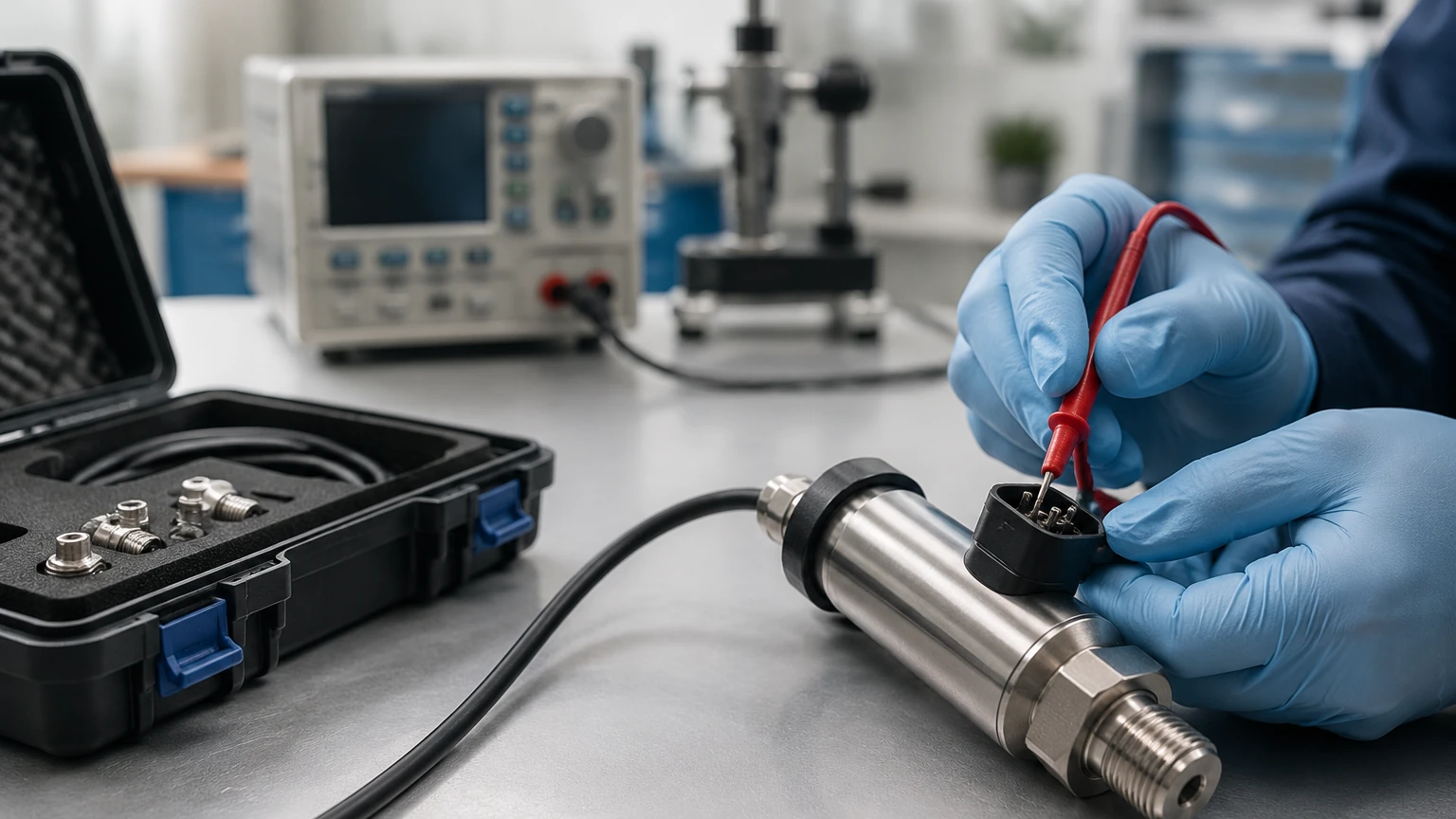
Ensure the transducer is clean and free of debris. Connect the transducer to a regulated pressure source and a high-accuracy digital multimeter or a dedicated calibrator. With zero pressure applied (atmospheric pressure for gauge sensors), the output should read exactly 4.000 mA (or 0V). If it does not, a "Zero Adjustment" is required.
2. The 5-Point Check
To verify linearity and hysteresis, apply pressure in increments of 25% of the full-scale range:
* 0% (Lower Range Value): Check for 4mA.
* 25%: Check for 8mA.
* 50%: Check for 12mA.
* 75%: Check for 16mA.
* 100% (Upper Range Value): Check for 20mA.
Repeat these steps in descending order (100% down to 0%) to identify hysteresis—the difference in readings when approaching a point from different directions.
3. Span Adjustment
If the output at 100% pressure is incorrect (e.g., 19.8mA instead of 20mA), the "Span" or "Gain" must be adjusted. Note that adjusting the span can sometimes affect the zero point, so an iterative process of checking zero and span is often necessary.
4. Documentation
Record the "As-Found" data (before adjustment) and "As-Left" data (after adjustment). This documentation is crucial for identifying trends in instrument drift over time.
Selection Criteria for Industrial Level Applications
Choosing the right instrument is as important as the calibration itself. Different applications require different transducer architectures. The following table provides a comparison for selection purposes.
| Feature | Submersible Hydrostatic Transducer | External Gauge Pressure Transmitter | Differential Pressure (DP) Cell |
| :— | :— | :— | :— |
| Primary Use | Open tanks, wells, reservoirs | Closed tanks (vented), pipelines | Pressurized tanks, boilers |
| Installation | Lowered into the media | Mounted via flange or NPT thread | Two-port connection (High/Low) |
| Maintenance | Easy to replace, hard to calibrate in-situ | Easy access for field calibration | Requires manifold for zeroing |
| Media Contact | Full immersion (requires chemical compatibility) | Diaphragm contact only | Diaphragm contact only |
| Accuracy | High (0.1% to 0.25% FS) | Moderate to High | Very High (0.05% FS) |
Installation and Environmental Considerations
Even a perfectly calibrated pressure transducer will provide inaccurate data if installed incorrectly. Key considerations include:
* Venting: For gauge pressure sensors, the back of the diaphragm must be vented to the atmosphere. In submersible models, this is achieved via a vent tube inside the cable. If this tube is blocked or kinked, the reading will drift with changes in barometric pressure.
* Temperature Compensation: Rapid temperature fluctuations can cause thermal expansion in the sensor housing. Ensure the transducer has internal temperature compensation or is installed away from direct heat sources.
* Mounting Position: Some high-sensitivity transducers are affected by orientation due to the weight of the internal oil fill. Always calibrate the unit in the same orientation in which it will be installed.
* Turbulence and Silt: In water treatment applications, avoid placing submersible sensors near agitators or in areas where silt can accumulate and block the sensing port.
Limitations and Potential Risks
While pressure transducer calibration improves reliability, users must be aware of inherent limitations:
1. Media Density Changes: Hydrostatic transducers measure weight, not volume. If the density ($
ho$) of the liquid changes due to temperature or concentration shifts, the level reading will be incorrect even if the pressure measurement is accurate.
2. Overpressure Damage: Exposing a transducer to pressures beyond its proof pressure (typically 1.5x to 3x the rated range) can permanently deform the diaphragm, leading to non-linear drift that cannot be calibrated out.
3. Long-term Stability: No sensor is perfectly stable. High-quality instruments from reputable manufacturers like Welk offer better long-term stability, reducing the required frequency of calibration cycles.
4. Electrical Interference: Improper shielding or grounding can introduce noise into the signal, which may be mistaken for sensor instability during calibration.
Frequently Asked Questions (FAQs)
Q: How often should I perform pressure transducer calibration?
A: For most industrial applications, an annual calibration is standard. However, in critical safety systems or harsh environments with high vibration, semi-annual or quarterly checks may be required.
Q: Can I calibrate a transducer while it is still installed in the process?
A: Yes, if the system is equipped with a 3-way or 5-way manifold. This allows you to isolate the sensor from the process and apply a known test pressure without removing the device.
Q: What is the difference between a factory calibration and a field calibration?
A: Factory calibration is performed under ideal laboratory conditions with primary standards. Field calibration is a verification and adjustment process performed at the site using portable secondary standards. Field calibration accounts for the specific environmental conditions of the installation.
Q: Why does my reading change when the weather changes?
A: This is likely due to a failure in the atmospheric vent. If the sensor cannot reference current barometric pressure, it will interpret a drop in weather-related air pressure as an increase in liquid level.
Q: What equipment is needed for pressure transducer calibration?
A: At a minimum, you need a pressure source (hand pump or deadweight tester), a reference gauge (at least 4 times more accurate than the device under test), and a signal reader (multimeter or HART communicator).
For professional-grade measurement solutions and technical support regarding hydrostatic and radar level technologies, engineers are encouraged to Review product options and application support to ensure their systems meet the highest standards of accuracy and durability.