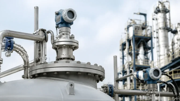
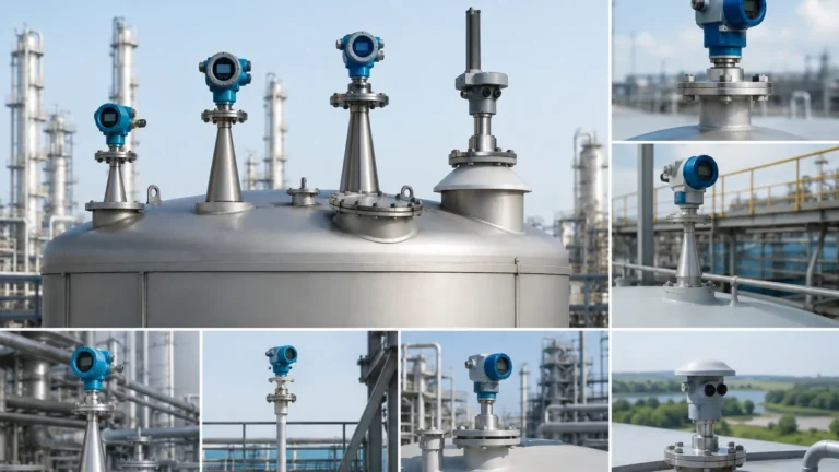
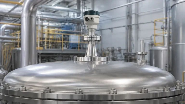
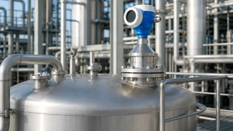
Micropilot Radar Level Transmitter
Micropilot Radar Level Transmitter: An Engineering Selection and Installation Guide
In the landscape of industrial process control, the accurate measurement of liquid and solid levels is fundamental to operational safety and efficiency. Among the various technologies available, the micropilot radar level transmitter has emerged as a preferred solution for demanding environments. Utilizing non-contact microwave technology, these instruments provide reliable data regardless of changes in pressure, temperature, or the presence of vapors.
As a professional manufacturer of industrial instrumentation, Welk provides advanced Radar Level Meters designed to meet the rigorous standards of the chemical, oil and gas, and water treatment sectors. This guide explores the measurement principles, selection criteria, and installation best practices for radar level transmitters to assist engineers in optimizing their process monitoring systems.
Measurement Principles of Radar Level Technology
Radar level transmitters operate on the principle of Time-of-Flight (ToF). The device emits high-frequency electromagnetic pulses (typically in the GHz range) via an antenna. These pulses travel at the speed of light, reach the surface of the medium, and are reflected back to the sensor.
Time of Flight (ToF) and Pulse Radar
In pulse radar systems, the transmitter measures the time interval between the emission of the pulse and its reception. The distance ($D$) from the reference point to the surface is calculated using the formula:
$$D = \frac{c \times t}{2}$$
Where:
* c is the speed of light.
* t is the measured transit time.
FMCW (Frequency Modulated Continuous Wave)
Modern high-precision instruments, such as the 80GHz micropilot radar level transmitter, often utilize Frequency Modulated Continuous Wave (FMCW) technology. Instead of a single pulse, the transmitter emits a continuous signal with a varying frequency. The difference between the emitted frequency and the received frequency at any given moment is proportional to the distance. FMCW offers superior resolution and signal-to-noise ratios, making it ideal for measuring low-dielectric liquids or applications with heavy surface turbulence.
The Role of Dielectric Constant ($ε_r$)
The reliability of a radar signal depends heavily on the dielectric constant of the medium. Materials with high dielectric constants (e.g., water, $ε_r ≈ 80$) reflect signals strongly. Materials with low dielectric constants (e.g., hydrocarbons, $ε_r < 2.0$) allow more energy to penetrate the surface, resulting in a weaker reflected signal. Modern radar level meters use sophisticated signal processing algorithms to extract these weak echoes from background noise.
—
Selection Criteria for Micropilot Radar Level Transmitters
Choosing the correct instrument requires a detailed analysis of the process conditions. The table below outlines the primary differences between common radar frequencies used in industrial applications.
Table 1: Comparison of Radar Frequencies
| Feature | 6 GHz Radar | 26 GHz Radar | 80 GHz Radar |
| :— | :— | :— | :— |
| Beam Angle | Wide (~20° – 30°) | Medium (~8° – 15°) | Narrow (~3° – 8°) |
| Antenna Size | Large | Medium | Small / Compact |
| Dust/Steam Resistance | Excellent | Good | Moderate (requires purging) |
| Accuracy | ±10 mm | ±3 mm | ±1 mm |
| Application | Large tanks, turbulence | Standard process tanks | Tall silos, narrow nozzles |
Key Selection Factors
1. Medium Properties: Is the material liquid, slurry, or solid? For solids, an 80GHz transmitter is often preferred due to its ability to handle uneven surfaces and low reflectivity. For liquids with heavy foam, lower frequencies (6GHz or 26GHz) may perform better as they are less likely to be absorbed by the foam layer.
2. Vessel Geometry: If the tank contains internal obstructions like agitators, heating coils, or ladders, a narrow beam angle (high frequency) is essential to avoid false echoes.
3. Process Environment: High temperatures (up to +250°C or higher with cooling) and high pressures (up to 40 bar or more) require specific flange designs and seal materials (e.g., PTFE, PEEK, or Kalrez).
4. Measurement Range: While some radar units can measure up to 120 meters, standard process tanks usually require a range of 10 to 30 meters.
—
Installation Considerations and Best Practices
Correct installation is the most critical factor in ensuring the longevity and accuracy of a micropilot radar level transmitter. Engineers should adhere to the following technical guidelines:
1. Nozzle Positioning
The antenna should not be installed in the center of a tank (to avoid multiple reflections from the tank walls) nor too close to the wall. A general rule is to install the device at a distance of 1/6th of the tank diameter from the wall.
2. Nozzle Height and Diameter
The nozzle should be as short as possible. If the nozzle is too long or has internal burrs, it can create "ringing" or parasitic reflections that interfere with the near-range measurement (the "blind zone"). For 80GHz units, the beam is narrow enough that it can often be installed on existing small-diameter nozzles without interference.
3. Avoiding Obstructions
The radar beam is cone-shaped. Any metal object within this cone will reflect the signal. If an obstruction (like a support beam) cannot be moved, the transmitter’s software must be used to perform a "false echo suppression" or "background mapping" to ignore these static signals.
4. Orientation
For liquid applications, the antenna must be perpendicular to the liquid surface. For solids, a swiveling flange (aiming device) is often used to point the radar beam at the angle of repose of the material to maximize signal return.
—
Technical Limitations and Application Risks
While radar is highly versatile, it is not a universal solution for every scenario. Engineers must be aware of the following limitations:
* Heavy Foam: Dense, thick foam (like shaving cream) can absorb the radar signal entirely, leading to a "loss of echo." In such cases, guided wave radar or ultrasonic sensors may be more appropriate, though low-frequency pulse radar is sometimes successful.
* Extreme Vacuum: While radar works in a vacuum, the sealing of the antenna becomes a critical failure point. Specialized high-vacuum flanges are required.
* Condensation and Buildup: Moisture or material buildup on the antenna lens can attenuate the signal. For applications with heavy condensation, antennas with a convex (drip-off) PTFE lens or integrated air purging systems should be specified.
* Dielectric Limits: If the dielectric constant of the medium is below 1.4, the reflection may be too weak for standard non-contact radar. A guided wave radar (GWR) or a stilling well might be necessary to concentrate the signal.
—

Buyer’s Checklist: Information Required for Procurement
When sourcing a micropilot radar level transmitter from an international manufacturer, providing complete technical data ensures the equipment is fit for purpose. International buyers should confirm the following:
1. Material Safety Data Sheet (MSDS): To determine the dielectric constant and chemical compatibility of the wetted parts.
2. Tank Drawings: Including height, diameter, nozzle positions, and internal obstructions.
3. Operating Parameters: Minimum/maximum temperature and pressure.
4. Output Requirements: 4-20mA HART is standard, but Modbus RS485, Profibus, or Foundation Fieldbus may be required for integration into specific PLC/DCS systems.
5. Certification: Specify if ATEX, IECEx, or SIL2/3 functional safety ratings are required for hazardous areas.
—
Frequently Asked Questions (FAQ)
Q: Can a radar level transmitter measure through a plastic tank lid?
A: Yes. Since plastic is non-conductive and has a low dielectric constant, radar signals can penetrate plastic or fiberglass tank tops, allowing for measurement without cutting a hole in the vessel. However, signal attenuation must be accounted for.
Q: What is the difference between "Blind Zone" and "Blocking Distance"?
A: These terms are often used interchangeably. They refer to the area directly below the antenna where the device cannot accurately measure because the pulse emission and reception happen too quickly for the electronics to distinguish. Typically, this is between 50mm and 300mm depending on the frequency.
Q: How often does a radar level meter need calibration?
A: Radar is a solid-state technology with no moving parts. Unlike pressure transmitters, it does not suffer from "drift." Calibration is usually performed once during commissioning. Periodic verification is recommended every 1-2 years depending on local regulations and the criticality of the process.
Q: Is 80GHz always better than 26GHz?
A: Not necessarily. While 80GHz offers a narrower beam and better precision, 26GHz is often more robust in applications with heavy steam or dust, as the longer wavelength can penetrate airborne particles more effectively.
Conclusion
The micropilot radar level transmitter represents the pinnacle of non-contact level measurement. By understanding the interaction between frequency, dielectric constants, and vessel geometry, engineers can select a solution that provides maintenance-free operation for years. Whether managing corrosive chemicals or bulk solids, the integration of high-quality Radar Level Meters is a strategic investment in process reliability and safety. For customized OEM/ODM requirements, consulting with a specialized manufacturer like Welk ensures that the instrument is tailored to the specific challenges of your industrial application.