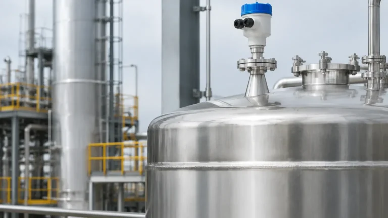
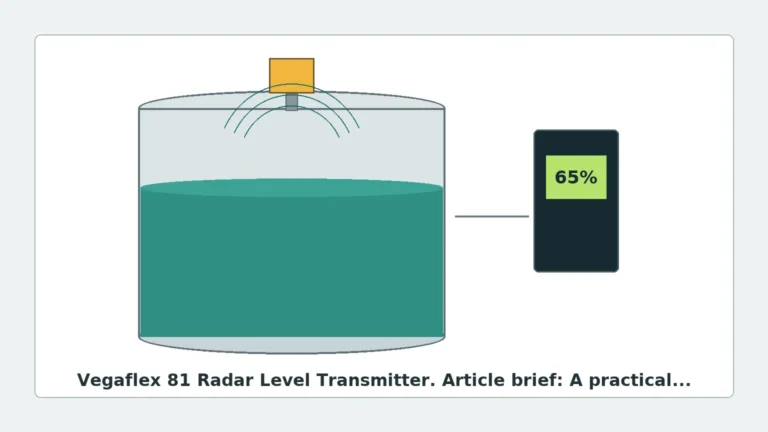
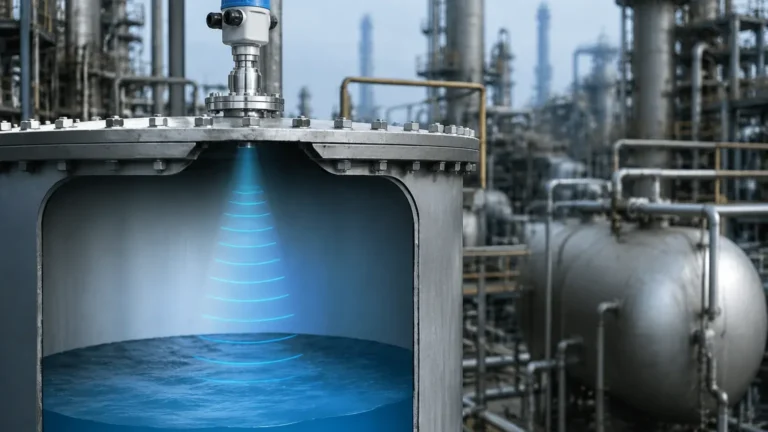
Mapping Radar Level Transmitter
Mapping Radar Level Transmitter: Engineering Guide for False Echo Suppression
In the field of industrial process automation, achieving accurate level measurement in complex tank environments is a significant challenge. Internal obstructions such as agitators, heating coils, ladders, and support beams often create parasitic reflections that can interfere with the primary signal. A mapping radar level transmitter is specifically designed to address these challenges through advanced signal processing known as false echo suppression or "static mapping."
This guide explores the technical principles, selection criteria, and installation best practices for utilizing Radar Level Meters in industrial applications where internal tank geometry complicates measurement.
1. Measurement Principles of Radar Level Technology
Before discussing the specifics of mapping, it is essential to understand how modern radar level instruments function. Most industrial radar sensors utilize one of two primary technologies: Pulse Radar or Frequency Modulated Continuous Wave (FMCW).
Pulse Radar (Time of Flight)
Pulse radar instruments emit short microwave pulses toward the medium surface. The instrument measures the time it takes for the pulse to travel to the surface and return to the antenna. Since the speed of electromagnetic waves is constant (the speed of light), the distance is calculated using the formula:
*Distance = (Speed of Light × Time of Flight) / 2*.
FMCW Radar
FMCW (Frequency Modulated Continuous Wave) radar transmits a continuous signal with a constantly changing frequency. The reflection from the product surface is received and mixed with the transmitted signal. The frequency difference between the transmitted and received signals is proportional to the distance. FMCW is generally preferred for high-precision applications due to its superior signal-to-noise ratio.
The Echo Curve
Regardless of the transmission method, the receiver generates an "echo curve." This curve represents the amplitude of reflected signals over distance. In an ideal, empty tank, the curve would be flat. However, in real-world industrial vessels, every internal structure reflects some energy, resulting in multiple peaks on the echo curve. This is where the functionality of a mapping radar level transmitter becomes critical.
2. What is a Mapping Radar Level Transmitter?
A mapping radar level transmitter refers to a device equipped with software algorithms capable of recording and "masking" static interference. This process is technically known as False Echo Suppression or Echo Mapping.
How Mapping Works
When a radar instrument is first installed, an "empty tank mapping" is performed. The transmitter scans the entire height of the vessel when the liquid level is at its lowest point. The software identifies all reflections caused by fixed internal structures (nozzles, weld seams, agitator shafts).
Once these static reflections are identified, the transmitter stores them in its memory as a "map." During normal operation, the transmitter subtracts this map from the live echo curve. Any new signal that appears above the mapped threshold is identified as the actual product level. This allows the instrument to "see through" obstructions that would otherwise cause measurement errors or signal loss.
3. Selecting the Right Radar Frequency
The effectiveness of a mapping radar level transmitter is heavily influenced by the operating frequency. Welk provides instruments across various frequency bands to suit different vessel geometries.
| Frequency Band | Beam Angle | Typical Application | Mapping Requirement |
| :— | :— | :— | :— |
| 6 GHz (C-Band) | Wide (approx. 23°) | Large outdoor tanks, heavy turbulence, foam. | High; wide beam hits many internal structures. |
| 26 GHz (K-Band) | Medium (approx. 8°-12°) | Standard process vessels, chemical storage. | Moderate; balanced performance. |
| 80 GHz (W-Band) | Narrow (approx. 3°-4°) | Small vessels, tall nozzles, complex internals. | Low; narrow beam avoids most obstructions. |
The 80 GHz Advantage
High-frequency 80 GHz radar level meters have become the industry standard for complex vessels. Because the beam is extremely narrow, it can often be directed between agitator blades and heating coils without hitting them. While mapping is still available on these units, the requirement for intensive software filtering is reduced because the physical beam avoids the obstacles entirely.
4. Installation Considerations and Constraints
Even the most advanced mapping radar level transmitter cannot compensate for a poor installation. To ensure reliable data, engineers must follow specific placement guidelines.
Nozzle Geometry
The antenna should ideally extend slightly below the bottom of the mounting nozzle. If the nozzle is too long or narrow, it creates "ringing" or internal reflections that can saturate the receiver. If a long nozzle is unavoidable, a mapping scan must be performed to eliminate the nozzle-end reflection.
Distance from Tank Wall
Radar sensors should not be mounted in the center of a tank (to avoid multiple reflections from the walls) nor too close to the wall (where the beam may interact with weld seams or scale buildup). A general rule of thumb is to mount the sensor at 1/6th of the tank diameter from the wall.
Avoiding the Vortex
In tanks with agitators, the liquid surface often forms a vortex. Mounting the radar directly over the center of the vortex can cause the signal to be deflected away from the antenna, leading to signal loss. The sensor should be positioned to hit a relatively flat area of the liquid surface.
Obstruction Clearance
While the mapping radar level transmitter can filter out static objects, it cannot see through them. If a large horizontal support beam completely blocks the path to the liquid, the radar will not receive a signal from the product. The mapping function is for filtering *interference*, not for bypassing total physical blockages.
5. Technical Selection Table for Industrial Applications
When choosing a radar instrument, consider the following technical parameters:
| Parameter | Requirement/Value |
| :— | :— |
| Measurement Range | Up to 30m (standard), 100m+ (specialized) |
| Accuracy | ±2mm to ±5mm (Pulse), ±1mm (FMCW) |
| Process Temperature | -40°C to +250°C (Standard), up to +450°C (High-temp) |
| Process Pressure | Vacuum to 40 bar (Standard), up to 160 bar (High-pressure) |
| Output Signal | 4-20mA HART, RS485 Modbus, Profibus PA |
| Dielectric Constant (εr) | ≥ 1.4 (Lower εr requires more sensitive electronics) |
6. Limitations and Application Risks
Despite the power of echo mapping, certain environmental factors can degrade performance:
* Heavy Foam: Some types of foam absorb radar signals entirely, while others reflect them. If the foam is thick and dense, the radar may measure the top of the foam instead of the liquid. In such cases, a guided wave radar or hydrostatic transmitter might be more appropriate.
* Low Dielectric Media: Materials like liquid nitrogen or certain hydrocarbons have very low dielectric constants (εr < 2.0). These materials reflect very little energy. If the reflection from a low-dielectric liquid is weaker than the "noise" from an unmapped obstruction, the measurement may fail.
* Condensation and Buildup: While mapping can ignore static objects, it cannot ignore buildup on the antenna itself. If the antenna becomes coated with a conductive or thick material, the signal strength will drop. Welk offers PTFE-enclosed antennas and air purging systems to mitigate this risk.
* Dynamic Obstructions: Mapping is designed for *static* objects. If an object moves (like a floating roof or a variable-position internal arm), a standard static map will not be effective. Advanced tracking algorithms are required for these scenarios.
7. Frequently Asked Questions (FAQ)
Q: Can I perform mapping while the tank is full?
A: No. For the most effective mapping, the tank should be as empty as possible. This allows the transmitter to "see" and record all the internal structures that would normally be submerged. If mapping is done while the tank is half-full, the transmitter can only map the obstructions in the top half of the vessel.
Q: Does mapping need to be redone if I change the process liquid?
A: Generally, no. Mapping is concerned with the physical structures of the tank. As long as the internal geometry hasn't changed (e.g., you haven't added a new ladder), the map remains valid. However, if the new liquid has a significantly lower dielectric constant, you may need to adjust the sensitivity settings.
Q: How does a mapping radar level transmitter handle agitators?
A: If the agitator is moving, it creates a dynamic reflection. Modern transmitters use "Agitator Mapping" or "Echo Tracking" where the software recognizes the rhythmic, moving nature of the agitator reflection and filters it out differently than a static wall or pipe.
Q: What is the difference between "Threshold" and "Map"?
A: A threshold is a simple horizontal line; any signal above it is considered a level. A map is a complex, distance-dependent curve that follows the actual "noise" profile of your specific tank. Mapping is significantly more accurate for complex vessels.
8. Conclusion for International Buyers
When sourcing a mapping radar level transmitter for industrial projects, it is vital to provide the manufacturer with a detailed tank drawing. Information regarding nozzle height, internal obstructions, and the dielectric constant of the medium is essential for pre-configuring the device.
Welk offers a comprehensive range of Radar Level Meters equipped with user-friendly mapping software, allowing for quick commissioning even in challenging environments. By combining high-frequency hardware (up to 80 GHz) with intelligent false echo suppression, these instruments provide the reliability required for modern industrial automation.
For successful implementation, always prioritize the narrowest possible beam angle for the application and ensure that the "Empty Tank Map" is recorded during the initial commissioning phase. This technical foundation ensures that your level measurement remains precise, regardless of the complexity of your process vessel.