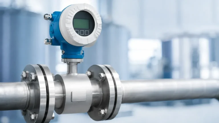
Flare Gas Ultrasonic Flow Meter
Flare Gas Ultrasonic Flow Meter
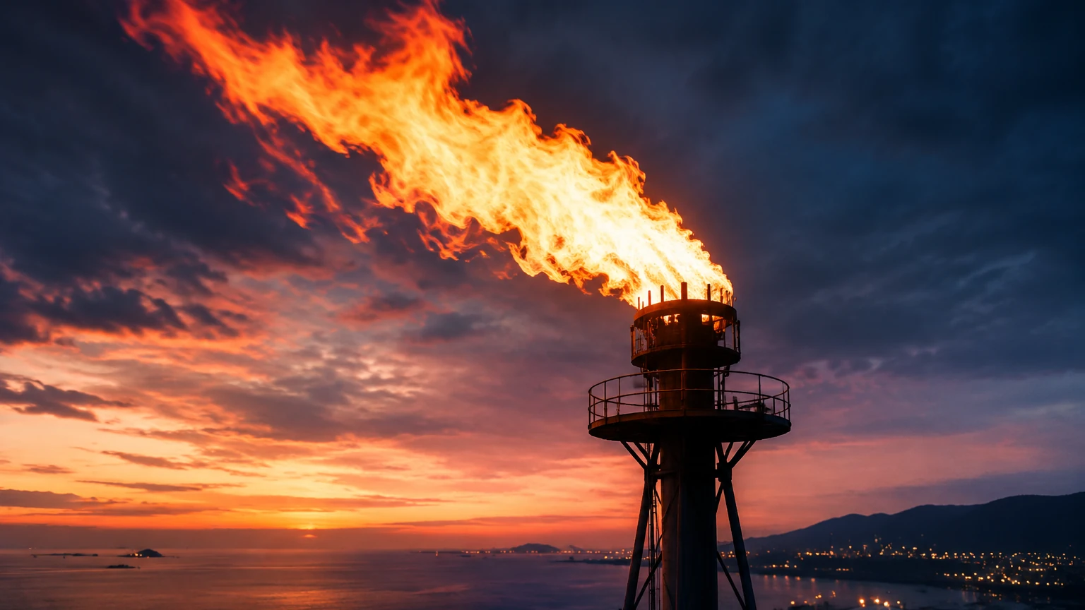
In industrial processing, flare systems serve as critical safety components, designed to dispose of waste gases during upsets, startups, and routine operations. Accurate measurement of flare gas is not only a regulatory requirement for environmental compliance and carbon emissions reporting but also a vital diagnostic tool for plant efficiency. The flare gas ultrasonic flow meter has emerged as the industry standard for this application due to its ability to handle wide velocity ranges and varying gas compositions without obstructing the flow path.
Understanding Flare Gas Measurement Challenges
Measuring flare gas is one of the most demanding tasks in industrial flow metering. Unlike controlled process flows, flare gas presents several unique challenges:
1. Extreme Velocity Range: Flow rates can vary from near-zero during normal standby conditions to over 100 meters per second (m/s) during an emergency blowdown.
2. Varying Gas Composition: Flare gas is often a mixture of hydrocarbons, hydrogen, nitrogen, and CO2. The molecular weight can change rapidly, affecting the physical properties of the gas.
3. Low Pressure: Flare headers typically operate at very low pressures, often close to atmospheric, which limits the effectiveness of differential pressure-based meters.
4. Contaminants: The presence of moisture, H2S, and particulate matter can lead to fouling or corrosion in traditional intrusive meters.
Measurement Principle: Transit-Time Ultrasonic Technology
A flare gas ultrasonic flow meter operates on the transit-time (or time-of-flight) principle. This method utilizes pairs of ultrasonic transducers mounted on the pipe, which send and receive acoustic pulses through the gas stream.
The Transit-Time Equation
When a sound pulse travels in the direction of the gas flow, its speed is increased by the flow velocity. Conversely, when traveling against the flow, its speed is decreased. The meter measures the time it takes for pulses to travel upstream ($t_{up}$) and downstream ($t_{dn}$).
* Velocity Calculation: The flow velocity ($v$) is proportional to the difference in these transit times. Because the distance between transducers ($L$) and the angle of the path ($ heta$) are known constants, the meter can calculate the average line velocity regardless of the speed of sound in the gas.
* Speed of Sound (SOS): By calculating the average of the transit times, the meter also determines the speed of sound within the gas. Since the SOS is directly related to the gas temperature and molecular weight, this data allows the system to estimate the composition and mass flow of the gas mixture.
This dual capability—measuring both velocity and SOS—is what makes the flare gas ultrasonic flow meter superior to thermal or mechanical meters in applications with fluctuating gas types.
Key Advantages of Ultrasonic Meters in Flare Systems
High Turndown Ratio
One of the most significant benefits is the turndown ratio, which can reach 4000:1. This allows the same instrument to accurately measure the "leakage" or sweep gas during idle periods and the massive volumes released during a relief event.
Non-Intrusive Design
Most ultrasonic meters use transducers that do not protrude significantly into the flow or use a spool-piece design that maintains a full-bore opening. This results in zero pressure drop and eliminates the risk of the meter being damaged by high-velocity debris or liquid slugs.
Maintenance and Reliability
Because there are no moving parts to wear out, these meters offer high long-term stability. Advanced digital signal processing (DSP) allows the meter to filter out background noise from valves or headers, ensuring a clean signal even in turbulent conditions.
Selection Criteria and Technical Specifications
Selecting the right flare gas ultrasonic flow meter requires a thorough analysis of the installation site and process conditions. Engineers should consider the following parameters:
| Feature | Specification / Requirement |
| :— | :— |
| Pipe Diameter | Typically 100 mm to 3000 mm (4" to 120") |
| Velocity Range | 0.03 m/s to 120 m/s (0.1 ft/s to 393 ft/s) |
| Accuracy | ±1% to ±5% of reading depending on calibration and path configuration |
| Operating Temperature | -200°C to +250°C (standard), higher with specialized buffers |
| Operating Pressure | Vacuum to 100 bar (though flare is usually low pressure) |
| Hazardous Area Rating | ATEX/IECEx Zone 1 or 2, Class I Div 1 |
| Transducer Material | Titanium, Stainless Steel 316L, or Hastelloy for corrosive gases |
When evaluating instrumentation for broader plant automation, including storage and containment, it is useful to consult specialized manufacturers. For comprehensive process control and level monitoring solutions, you can Review product options and application support on our Main Page to ensure all aspects of your fluid and gas management are covered.
Comparison of Flare Measurement Technologies
While ultrasonic is the preferred choice, other technologies are sometimes used. The table below highlights why ultrasonic is often selected for critical flare applications.
| Technology | Accuracy | Turndown | Composition Sensitivity | Pressure Drop |
| :— | :— | :— | :— | :— |
| Ultrasonic | High | Excellent (4000:1) | Low (Measures SOS) | Zero |
| Thermal Mass | Medium | Good (100:1) | High (Needs constant gas mix) | Low |
| Differential Pressure | Low | Poor (10:1) | Medium | High |
| Insertion Turbine | Medium | Poor (20:1) | Low | Low |
Installation Guidelines for Optimal Performance
To achieve the specified accuracy, the installation must adhere to strict engineering standards. The performance of a flare gas ultrasonic flow meter is heavily dependent on the flow profile.
Straight Pipe Runs
Standard installations typically require a minimum of 20 diameters (D) of straight pipe upstream and 5D downstream of the meter. If these distances are not available due to space constraints, flow conditioners may be used, though they introduce pressure drop and potential fouling points. Alternatively, multi-path ultrasonic meters (using 2 or 4 paths) can compensate for distorted flow profiles better than single-path versions.
Transducer Orientation
Transducers should be mounted in the horizontal plane (3 o'clock and 9 o'clock positions) to prevent the accumulation of liquids or condensate on the transducer faces, which can attenuate the ultrasonic signal.
Access and Safety
Since flare lines are often elevated, providing permanent platforms for maintenance is recommended. Retraction mechanisms (hot-tapping valves) allow for the removal and inspection of transducers without shutting down the flare system, which is a critical feature for continuous processes.
Limitations and Operational Considerations
While highly versatile, ultrasonic meters have limitations:
* Acoustic Noise: High-frequency noise from nearby pressure-reducing valves can interfere with the ultrasonic signal. Specialized noise-dampening insulation or frequency-shifting software may be required.
* Liquid Slugs: While the meter can handle moisture, a solid "wall" of liquid (slug) will block the ultrasonic signal entirely until the slug passes.
* Gas Attenuation: Certain gases, particularly high concentrations of CO2 or very low-pressure Hydrogen, can absorb ultrasonic energy more than others. In these cases, high-power transducers or lower-frequency signals are necessary to maintain a reliable measurement.
Frequently Asked Questions (FAQs)
Q: How does the meter handle changing gas compositions?
A: The meter measures the Speed of Sound (SOS). By combining the SOS with temperature and pressure data, the meter's internal computer can calculate the molecular weight of the gas, allowing for accurate mass flow conversion even as the gas mix changes.
Q: Can ultrasonic flow meters be installed on existing flare lines?
A: Yes, through a process called "hot tapping," transducers can be installed on existing lines while they are in service, provided the pipe material and wall thickness are suitable.
Q: What maintenance is required for a flare gas ultrasonic flow meter?
A: Maintenance is minimal. Periodic checks of the signal strength and diagnostic parameters (such as Gain and Signal-to-Noise Ratio) are usually sufficient. If the gas is particularly dirty, transducers may need occasional cleaning.
Q: Why is molecular weight calculation important in flare applications?
A: Environmental regulations often require reporting the mass of emissions (e.g., kilograms of CO2). Since the meter measures volume, knowing the molecular weight via the speed of sound is the only way to accurately convert that volume to mass without an expensive online gas chromatograph.
By understanding these principles and selection criteria, engineering teams can ensure that their flare gas ultrasonic flow meter provides reliable data for both safety and environmental compliance. For those managing complex industrial sites, integrating these flow solutions with robust level measurement is key to total process visibility.