Level Pressure Transducer
Level Pressure Transducer
In industrial process control, the level pressure transducer—often referred to as a hydrostatic level transmitter—serves as a fundamental tool for monitoring liquid volumes in tanks, wells, and reservoirs. Unlike non-contact methods such as radar or ultrasonic sensing, the level pressure transducer relies on the physical relationship between the height of a liquid and the pressure it exerts at a specific depth. This method is valued for its reliability, ease of installation, and cost-effectiveness in a wide range of applications, from municipal water treatment to complex chemical processing.
As a professional manufacturer, Welk provides a diverse portfolio of industrial level measurement instruments. Understanding the technical nuances of level pressure transducers is essential for engineers and procurement specialists seeking to optimize their automation systems. This guide explores the principles, selection criteria, and practical implementation of these devices.
Measurement Principles of Hydrostatic Level Transducers
The operation of a level pressure transducer is based on the hydrostatic paradox: the pressure at a specific point in a static fluid is directly proportional to the height of the liquid column above that point, regardless of the tank's shape or volume.
The Fundamental Equation
The mathematical foundation for this measurement is expressed as:
P = ρ · g · h
Where:
* P is the hydrostatic pressure (typically measured in bar, kPa, or psi).
* ρ (rho) is the density of the liquid (kg/m³).
* g is the acceleration due to gravity (approximately 9.81 m/s²).
* h is the height of the liquid column (meters or feet).
Because gravity is constant and the density of most liquids (like water) is known, the pressure measured by the transducer can be converted directly into a level reading. For example, in a tank of water at 4°C, every 1 meter (3.28 ft) of depth generates approximately 9.81 kPa (0.098 bar or 1.42 psi) of pressure.
Atmospheric Pressure Compensation
A critical aspect of using a level pressure transducer in vented (open) tanks is compensating for changes in atmospheric pressure. If the transducer only measured absolute pressure, fluctuations in weather or altitude would cause errors in the level reading.
To solve this, most industrial transducers use a "gauge pressure" reference. This is achieved via a small vent tube running through the length of the sensor cable, which allows the internal side of the sensing diaphragm to be exposed to the current atmospheric pressure. This effectively cancels out the atmospheric component, ensuring the sensor only measures the pressure exerted by the liquid itself.
Types of Level Pressure Transducers
Depending on the installation environment and the nature of the medium, level pressure transducers are generally categorized into two primary designs: submersible and externally mounted.
Submersible Level Transmitters
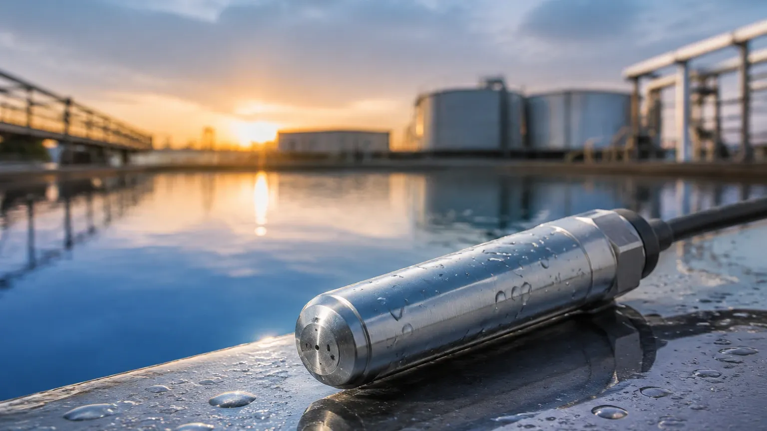
These sensors are designed to be lowered directly into the liquid. They are housed in a waterproof (IP68) enclosure, typically made of 316L stainless steel. The sensor is suspended by its own cable, which contains the electrical wires and the atmospheric vent tube. Submersible models are ideal for deep wells, boreholes, and large open reservoirs where mounting a sensor at the bottom of a tank wall is not feasible.
Externally Mounted (Pressure) Transmitters
For closed tanks or process vessels with existing plumbing, transducers are mounted externally. These are connected via threaded ports, flanges, or sanitary fittings at the bottom or side of the vessel. These units are easier to maintain as they do not require the sensor to be pulled out of the liquid for inspection. In pressurized tanks, a differential pressure (DP) transmitter is used instead, measuring the difference between the bottom liquid pressure and the top gas-space pressure.
Practical Selection Criteria
Selecting the correct level pressure transducer requires a detailed analysis of the application environment. Engineers should consult the Main Page of the manufacturer's technical catalog to compare specific model specifications against the following criteria:
1. Media Compatibility and Material Selection
The wetted parts of the transducer must be chemically compatible with the liquid. While 316L stainless steel is the standard for water and light oils, aggressive chemicals may require specialized materials:
* Ceramic Diaphragms: Highly resistant to abrasion and many corrosive acids.
* Hastelloy or Tantalum: Used for extremely aggressive chemical environments.
* PVC or PTFE Housings: Preferred for applications involving strong acids or plating baths where metal housings would corrode.
2. Pressure Range and Overpressure Protection
The sensor's range should be closely matched to the maximum expected liquid height. Selecting a sensor with too wide a range (e.g., a 100m range sensor for a 5m tank) will result in poor resolution and accuracy. Conversely, the sensor must have sufficient overpressure protection to survive accidental tank overfills or pressure surges.
3. Accuracy and Signal Output
Standard industrial transducers offer accuracy ranging from 0.5% to 0.1% of the full scale. For B2B applications, the common output signal is 4-20mA (2-wire), which is robust against electrical noise over long distances. Digital protocols like HART, RS485 (Modbus), or Profibus are increasingly used for remote diagnostics and configuration.
Selection Summary Table
| Feature | Submersible Transducer | External Pressure Transducer |
| :— | :— | :— |
| Installation | Suspended by cable into the liquid | Threaded or flanged to tank wall |
| Best Use Case | Deep wells, reservoirs, lift stations | Process tanks, hygienic applications |
| Maintenance | Requires lifting the unit out | Can be isolated with valves |
| Protection | IP68 (Permanent immersion) | IP65/IP67 (Splash proof) |
| Ventilation | Integrated vent tube in cable | Venting via housing or DP capillary |
Installation Considerations and Best Practices
Correct installation is paramount to the longevity and accuracy of a level pressure transducer. Even the highest quality instrument will fail or provide false data if environmental factors are ignored.
Avoiding Turbulence and Physical Damage
In tanks with agitators or high-velocity inflow, the sensor may move or be subjected to "pressure spikes." For submersible units, it is recommended to use a stilling well (a perforated pipe) to shield the sensor from turbulent currents. If a stilling well is not available, the sensor should be anchored or weighted to prevent it from swinging.
Cable Management and Venting
The cable of a submersible level pressure transducer is a critical component. It should not be kinked, as this can block the internal vent tube. The end of the cable (where it connects to the junction box) must be kept in a dry environment. Desiccant cartridges or specialized vent filters are often used at the termination point to prevent moisture from entering the vent tube, which could cause internal corrosion or measurement drift.
Zero and Span Calibration
Upon installation, it is standard practice to perform a zero-point calibration. This ensures that the sensor reads zero when the tank is empty. Because density can vary with temperature, some high-end transducers include integrated temperature sensors to provide real-time density compensation, maintaining accuracy across seasonal temperature shifts.
Limitations and Technical Boundaries
While highly versatile, the level pressure transducer is not a "one-size-fits-all" solution. Engineers must be aware of its inherent limitations:
1. Density Sensitivity: Since the measurement is based on weight, any change in the liquid's density (caused by temperature changes or concentration shifts) will change the pressure reading, even if the actual level remains constant.
2. Pressurized Vessels: In a sealed tank with a pressurized gas blanket (e.g., a carbonated beverage tank), a standard hydrostatic transducer will measure the sum of the liquid pressure and the gas pressure. In these cases, a differential pressure system is required.
3. Sediment and Clogging: In wastewater or slurries, solids can accumulate around the diaphragm. Flush-diaphragm designs or "clog-free" cages are necessary for these environments to prevent measurement lag or sensor failure.
Frequently Asked Questions (FAQs)
Q: Can a level pressure transducer be used for boiling liquids?
A: It is generally not recommended for direct contact with boiling liquids unless a cooling siphon or remote seal is used. High temperatures can damage the internal electronics and the steam bubbles can create "noise" in the pressure signal.
Q: How often should the sensor be calibrated?
A: For most industrial applications, an annual calibration check is sufficient. However, in critical safety or custody transfer applications, semi-annual calibration is recommended to account for potential sensor drift.
Q: What is the maximum depth a submersible transducer can measure?
A: Standard models can often reach depths of 200 meters (approx. 650 ft). Custom-engineered solutions from manufacturers like Welk can extend this range for deep-well monitoring and subsea applications.
Q: Does the shape of the tank affect the reading?
A: No. The hydrostatic pressure at the bottom of a 5-meter deep conical tank is exactly the same as the pressure at the bottom of a 5-meter deep cylindrical tank, provided the liquid density is the same. This makes pressure transducers very useful for irregularly shaped vessels.
For technical support and to explore the full range of level measurement technologies, including radar and ultrasonic alternatives, please visit the Main Page for detailed product data sheets and application engineering assistance.