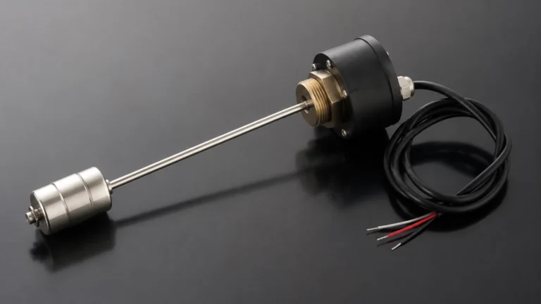
Flowmeter Dp
Flowmeter Dp
Differential pressure (DP) flow measurement remains one of the most prevalent methods for quantifying fluid movement in industrial processes. A flowmeter dp system operates on a well-established physical principle, utilizing a constriction within a pipe to create a pressure drop that is proportional to the square of the flow rate. This technology is valued for its versatility, reliability, and the lack of moving parts in the primary sensing element, making it a staple in water treatment, chemical processing, and oil and gas industries.
Understanding the mechanics, selection criteria, and installation requirements of a flowmeter dp is essential for engineers and plant operators seeking accurate process control. As a professional manufacturer of industrial instrumentation, Welk provides the technical foundation necessary to integrate these systems into complex automation environments.
Measurement Principles of Flowmeter Dp
The fundamental principle behind a flowmeter dp is Bernoulli’s Equation, which describes the relationship between pressure and velocity in a moving fluid. When a fluid stream encounters a restriction (the primary element) in a pipe, its velocity increases. According to the law of conservation of energy, this increase in kinetic energy must be balanced by a decrease in static pressure.
The resulting difference in pressure between the upstream side of the restriction and the downstream side (or the point of maximum constriction, known as the vena contracta) is the "differential pressure." The mathematical relationship is expressed as:
Q = k × √ΔP
Where:
* Q is the flow rate.
* k is a constant derived from the pipe diameter, the orifice diameter (beta ratio), and fluid properties.
* ΔP is the differential pressure measured.
A complete flowmeter dp system consists of two main components:
1. Primary Element: The physical restriction placed in the pipe (e.g., an orifice plate, Venturi tube, or flow nozzle).
2. Secondary Element: The differential pressure transmitter that senses the pressure difference and converts it into an electrical signal (typically 4-20mA or digital HART/Fieldbus).
Types of Primary Elements
Choosing the correct primary element is the most critical step in designing a flowmeter dp system. Each type offers different balances of accuracy, pressure recovery, and resistance to wear.
Orifice Plates
The orifice plate is the most common primary element due to its simplicity and cost-effectiveness. It is a thin metal plate with a precisely machined hole. While highly accurate when manufactured to standards like ISO 5167, it creates a significant permanent pressure loss in the system.
Venturi Tubes
Venturi tubes feature a tapered inlet and outlet. This geometry allows for much higher pressure recovery compared to orifice plates. They are ideal for applications where pumping costs must be minimized or where the fluid contains suspended solids that might accumulate behind an orifice plate.
Flow Nozzles
Flow nozzles are often used in high-velocity applications, such as steam flow measurement in power plants. They are more transitionally shaped than orifice plates, providing better durability against erosion at high temperatures and speeds.
Pitot Tubes and Averaging Pitot Tubes
Unlike other elements that restrict the entire flow stream, Pitot tubes measure the impact pressure at specific points. Averaging Pitot tubes use multiple sensing ports across the pipe diameter to provide a representative flow profile, making them suitable for very large pipe diameters where a full-bore restriction would be impractical.
Selection Criteria for Industrial Applications
When evaluating a flowmeter dp for a specific project, engineers must consider several technical factors to ensure long-term performance. For comprehensive hardware options and technical specifications, professionals often consult the Main Page of instrumentation providers to match sensors with process requirements.
| Feature | Orifice Plate | Venturi Tube | Flow Nozzle | Pitot Tube |
| :— | :— | :— | :— | :— |
| Accuracy | ±0.5% to ±2% | ±0.5% to ±1.5% | ±1% to ±2% | ±1% to ±4% |
| Pressure Loss | High | Low | Medium | Very Low |
| Initial Cost | Low | High | Medium | Low |
| Suitability | Clean Liquids/Gases | Slurries/High Flow | High Velocity/Steam | Large Pipes/Air |
| Installation | Easy | Difficult (Heavy) | Moderate | Very Easy |
Fluid Properties
The viscosity and density of the fluid significantly impact the Reynolds number (Re). Flowmeter dp systems are generally most accurate in turbulent flow regimes (High Re). If the fluid is highly viscous or the flow rate is very low (laminar flow), special calibrations or alternative technologies may be required.
Rangeability (Turndown Ratio)
A standard flowmeter dp typically has a turndown ratio of 3:1 or 4:1. This is because the relationship between flow and pressure is a square root. At 10% of the maximum flow, the differential pressure is only 1% of the full-scale DP, which can lead to measurement errors if the transmitter is not highly sensitive.
Installation Considerations and Best Practices
The accuracy of a flowmeter dp is highly dependent on how it is installed. Improper piping can lead to swirl and non-uniform velocity profiles, which invalidate the standard discharge coefficients used in flow calculations.
Straight Pipe Runs
To ensure a fully developed flow profile, primary elements require a specific length of straight pipe both upstream and downstream.
* Upstream: Usually 10 to 40 pipe diameters (D), depending on the presence of elbows, valves, or reducers.
* Downstream: Usually 5 to 10 pipe diameters (D).
If these distances cannot be met, flow conditioners or straightening vanes must be installed.
Impulse Line Piping
The impulse lines connect the primary element to the DP transmitter.
* For Liquids: The transmitter should be mounted below the primary element so that air bubbles can rise back into the main pipe.
* For Gases: The transmitter should be mounted above the primary element so that any condensate can drain back into the process line.
* Slope: Impulse lines should have a slope of at least 1:12 to prevent trapping of gas or liquid pockets.
Manifolds
A 3-valve or 5-valve manifold is essential for maintenance. It allows the operator to isolate the transmitter from the process, equalize the pressure for zero-checking, and bleed or vent the lines safely.

Limitations and Common Risks
While robust, the flowmeter dp technology has specific limitations that must be managed:
1. Permanent Pressure Loss (PPL): A portion of the pressure drop created by the restriction is never recovered. In large-scale operations, this translates to increased energy consumption by pumps or compressors.
2. Wear and Erosion: The sharp edge of an orifice plate is critical for accuracy. Over time, abrasive fluids can dull this edge, leading to a shift in measurement (usually under-reading the flow).
3. Impulse Line Clogging: In dirty or viscous applications, the small-diameter impulse lines can become blocked. This requires regular flushing or the use of remote seals (diaphragm seals) to isolate the transmitter from the process fluid.
4. Square Root Sensitivity: As mentioned, the accuracy diminishes at the lower end of the flow range. Modern multivariable transmitters can mitigate this somewhat, but it remains a physical constraint of the technology.
Frequently Asked Questions (FAQ)
Q: Can a flowmeter dp measure bi-directional flow?
A: Standard orifice plates are unidirectional. However, specialized symmetrical primary elements and bi-directional DP transmitters can be used for applications where flow direction changes.
Q: How often should an orifice plate be inspected?
A: This depends on the fluid. For clean water, an annual inspection may suffice. For abrasive or corrosive chemicals, quarterly checks may be necessary to ensure the plate edge remains sharp and the plate is not warped.
Q: What is the difference between a flowmeter dp and an ultrasonic flowmeter?
A: A flowmeter dp is an intrusive technology that creates a pressure drop, whereas ultrasonic meters are typically non-intrusive (clamp-on) and do not cause pressure loss. DP meters are often preferred for high-temperature steam or where a mechanical primary element is required for safety standards.
Q: How do I handle fluids that might freeze in the impulse lines?
A: In cold climates, impulse lines should be heat-traced (electric or steam) and insulated to prevent freezing or to maintain the viscosity of the fluid for accurate transmission of pressure.
Conclusion
The flowmeter dp remains a cornerstone of industrial flow measurement due to its predictable performance and extensive standardization. By carefully selecting the primary element—whether an orifice plate for cost-efficiency or a Venturi tube for energy savings—and adhering to strict installation guidelines, facilities can achieve highly reliable data for process optimization. For those integrating these sensors into broader automation systems, reviewing the latest transmitter technologies on the Main Page can provide the necessary insights into digital integration and advanced diagnostics. Proper maintenance of both the primary and secondary elements ensures that the flowmeter dp continues to provide value throughout the lifecycle of the industrial plant.