Boiler Management Software
Boiler Management Software
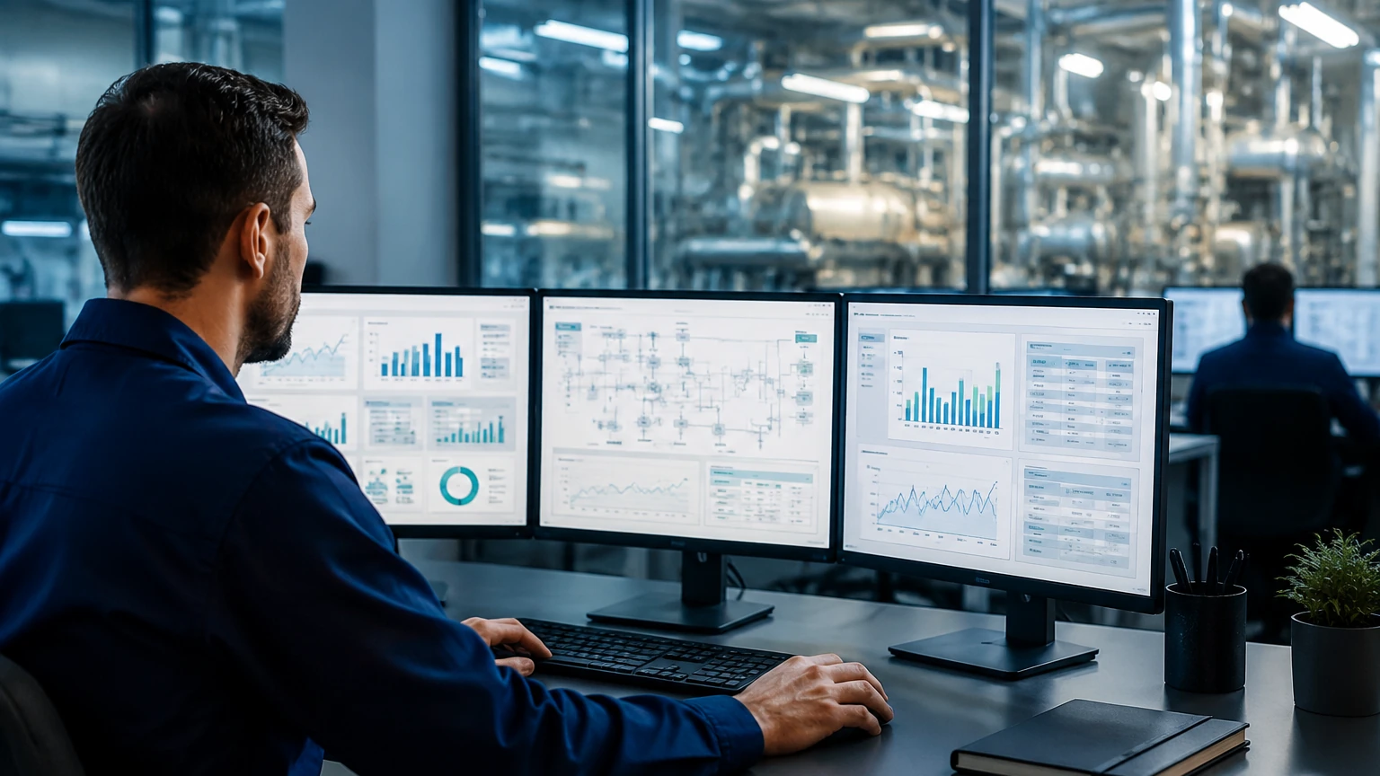
In the modern industrial landscape, the efficiency and safety of steam and hot water production are paramount. Boiler management software has emerged as a critical tool for plant engineers and facility managers, providing a centralized platform to monitor, control, and optimize boiler operations. While the software serves as the "brain" of the system, its effectiveness is entirely dependent on the quality and accuracy of the data it receives from field instrumentation. For industries ranging from chemical processing to food production, integrating robust boiler management software with high-precision level measurement instruments is no longer optional—it is a requirement for operational excellence.
The Role of Software in Boiler Operations
Boiler management software is designed to interface with Burner Management Systems (BMS) and Combustion Control Systems (CCS). Its primary function is to aggregate data from various sensors—pressure transmitters, temperature probes, and level meters—to provide a comprehensive view of the boiler’s health. By utilizing this software, operators can achieve several key objectives:
1. Safety Interlocks: Ensuring that the boiler does not operate under dangerous conditions, such as low water levels or excessive pressure.
2. Efficiency Optimization: Adjusting the fuel-to-air ratio and monitoring blowdown cycles to minimize energy waste.
3. Compliance and Reporting: Automatically generating logs for regulatory bodies regarding emissions and safety tests.
4. Predictive Maintenance: Identifying trends in sensor data that suggest a component is nearing failure before a shutdown occurs.
Fundamental Measurement Principles for Boiler Control
To understand how boiler management software processes information, one must first understand the physics behind the measurements. In boiler applications, level measurement is arguably the most critical variable. If the water level is too high, moisture can enter the steam lines (carryover), damaging turbines and heat exchangers. If it is too low, the boiler tubes can overheat and fail catastrophically.
Hydrostatic Level Measurement
Hydrostatic transmitters measure the pressure exerted by the liquid column. The principle is based on the formula:
P = ρ × g × h
Where *P* is pressure, *ρ* (rho) is the fluid density, *g* is gravity, and *h* is the height of the liquid. In a pressurized boiler, a differential pressure (DP) transmitter is typically used to subtract the steam space pressure from the total pressure at the bottom of the drum. A significant limitation here is that water density changes with temperature. Advanced boiler management software must include compensation algorithms to correct these readings as the boiler heats up.
Guided Wave Radar (GWR)
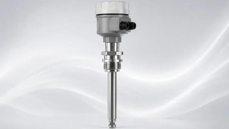
Radar level meters utilize Time Domain Reflectometry (TDR). A low-energy electromagnetic pulse is sent down a probe. When the pulse hits the water surface, a portion of the energy is reflected back to the transmitter. The distance is calculated as:
d = (c × t) / 2
Where *c* is the speed of light and *t* is the transit time. Unlike hydrostatic sensors, radar is largely unaffected by changes in fluid density. However, in high-pressure steam environments, the dielectric constant of the steam space increases, which can slow down the pulse. High-end radar units used in conjunction with boiler management software often feature a "gas phase compensation" reference to maintain accuracy.
Magnetic Level Gauges
These instruments use a float containing a magnet assembly that moves with the liquid level inside a bypass chamber. As the float moves, it flips magnetic flags on an external scale and can also trigger reed switches or transmit a 4-20mA signal via a magnetostrictive sensor. This provides a mechanical backup that is highly visible to operators while feeding electronic data into the management software.
Key Evaluation Criteria for Boiler Management Software
When selecting a software suite to manage boiler assets, several technical factors must be evaluated to ensure compatibility with existing hardware, such as those found on the Main Page of industrial instrument providers.
* Data Integration Protocols: The software should support standard industrial protocols like Modbus TCP/IP, Profibus, or HART. This ensures seamless communication with level transmitters and flow meters.
* Real-time Visualization: The interface must provide a clear, real-time HMI (Human Machine Interface) showing the water level, steam pressure, and stack temperature.
* Alarm Management: Software should allow for the configuration of multiple alarm tiers (High, High-High, Low, Low-Low) with dedicated logging for each event.
* Scalability: For facilities with multiple boiler rooms, the software should be able to aggregate data from several locations into a single dashboard.
Technical Selection Table: Level Instruments for Boiler Software
| Technology | Accuracy | Temperature Range | Pressure Range | Ideal Use Case |
| :— | :— | :— | :— | :— |
| Guided Wave Radar | ±2 mm | Up to 450°C | Up to 400 bar | High-pressure steam drums requiring high precision. |
| Differential Pressure | ±0.075% Span | Process Dependent | Up to 600 bar | General level monitoring with density compensation. |
| Magnetic Gauge | ±5 mm | Up to 400°C | Up to 250 bar | Redundant visual indication and remote transmission. |
| Ultrasonic | ±0.25% Range | Up to 80°C | Up to 3 bar | Feedwater tank monitoring (non-pressurized). |
Installation Considerations and Best Practices
Proper installation of the sensors feeding the boiler management software is vital for system reliability. Even the most advanced software cannot correct for data noise caused by poor mechanical installation.
1. Stilling Wells and Bypass Chambers: To avoid turbulence caused by the rapid boiling of water (ebullition), level sensors should be installed in a stilling well or an external bypass chamber. This provides a stable surface for radar or float-based measurements.
2. Thermal Insulation: While sensors are designed for high temperatures, the electronics housing should be protected. In many cases, the transmitter is offset from the boiler body to allow for heat dissipation.
3. Steam Compensation: For GWR sensors, ensure the probe length is correctly calibrated for the specific height of the drum. If using DP transmitters, impulse lines must be kept clear of debris and properly sloped to prevent air pockets or condensate blockages.
4. Software Calibration: Once the hardware is installed, the boiler management software must be calibrated to match the physical "Zero" and "Span" of the vessel. This often involves a cold-fill test and a hot-start verification.
Limitations and Common Risks
While boiler management software significantly enhances safety, it is not without risks. Users should be aware of the following limitations:
* Signal Latency: In poorly optimized networks, there may be a delay between a physical level change and the software's reaction. This is critical for low-water cut-off functions.
* Sensor Fouling: Scaling and mineral buildup on level probes can lead to false readings. The software should be configured to detect "frozen" signals that indicate a stuck float or a coated radar probe.
* Cybersecurity: As boiler systems become more connected, they become targets for cyber-attacks. Management software must be protected by robust firewalls and strict access controls.
* Complexity Overload: An overly complex software interface can overwhelm operators during an emergency. The HMI should prioritize critical safety data over secondary efficiency metrics.
Frequently Asked Questions (FAQs)
Q: Can boiler management software replace a physical low-water cut-off switch?
A: No. While the software provides monitoring and control, safety standards (such as ASME CSD-1 or EN 12952) typically require independent, hard-wired mechanical or electronic low-water cut-off switches that operate regardless of the software state.
Q: How does the software handle foaming in the boiler?
A: Foaming can confuse some level sensors. Advanced software can be programmed to recognize the erratic signal patterns associated with foam and trigger a surface blowdown or alert the operator to check water chemistry.
Q: Is it possible to integrate legacy boilers into modern management software?
A: Yes, provided that the legacy boilers are retrofitted with modern transmitters (4-20mA or digital) and a compatible PLC (Programmable Logic Controller) to bridge the gap between the mechanical hardware and the digital software.
Q: What is the maintenance cycle for a system controlled by boiler management software?
A: While the software requires periodic updates and database optimization, the field instruments (level meters, pressure sensors) usually require calibration checks every 6 to 12 months, depending on the severity of the service and local regulations.
Conclusion
Boiler management software represents the pinnacle of thermal process control, offering a sophisticated way to manage complex energy systems. However, the integrity of the entire system rests on the accuracy of the level measurement instruments installed at the process interface. By selecting the appropriate measurement principle—whether it be guided wave radar for high-pressure precision or magnetic gauges for reliable redundancy—and ensuring professional installation, industrial operators can leverage software to achieve maximum uptime and safety. For those looking to explore specific hardware options that integrate with these digital solutions, reviewing the technical specifications on the Main Page of a dedicated instrument manufacturer is a recommended next step in the engineering process.