Surface Mount Pressure Sensor
Surface Mount Pressure Sensor
In the landscape of industrial automation and process control, the term "surface mount pressure sensor" encompasses a broad spectrum of technologies, ranging from board-level micro-electromechanical systems (MEMS) used in localized pneumatic control to heavy-duty industrial transmitters featuring flush-mount diaphragms. For process engineers and system integrators, selecting the correct pressure sensing architecture is critical for ensuring long-term accuracy, safety, and reliability in demanding environments such as water treatment, chemical processing, and oil and gas production.
This guide examines the technical principles, application criteria, and installation best practices for surface mount pressure sensing technology, specifically focusing on its role in industrial level and pressure measurement. For those seeking specific product specifications or engineering support, reviewing the Main Page of industrial instrumentation providers is recommended to align sensor capabilities with specific process requirements.
1. Understanding the Measurement Principles
Before selecting a surface mount pressure sensor, it is essential to understand the underlying physics that govern how these devices convert physical force into a readable electrical signal. In industrial contexts, most sensors utilize one of two primary sensing technologies: piezoresistive or ceramic capacitive.
1.1 Piezoresistive Sensing
Piezoresistive sensors are among the most common in industrial applications. They consist of a diaphragm—usually made of stainless steel or silicon—with strain gauges integrated into the surface. When pressure is applied, the diaphragm deforms slightly, changing the electrical resistance of the strain gauges. This change is measured via a Wheatstone bridge circuit and converted into a standardized output signal (such as 4-20mA or 0-10V).
1.2 Ceramic Capacitive Sensing
Ceramic capacitive sensors utilize a dry sensing cell where a ceramic diaphragm acts as one plate of a capacitor. As pressure moves the diaphragm closer to a fixed ceramic substrate, the capacitance changes. This technology is highly valued for its robustness against overpressure and its resistance to aggressive chemical media, as the ceramic material is inherently more inert than many metals.
1.3 Hydrostatic Level Measurement
In the context of level measurement, a surface mount pressure sensor functions as a hydrostatic level transmitter. The principle relies on the relationship between the height of a liquid column and the pressure exerted at the bottom of the vessel. The formula used is:
P = ρ × g × h
Where:
* P is the hydrostatic pressure (typically measured in bar or kPa).
* ρ (rho) is the density of the liquid (kg/m³).
* g is the gravitational acceleration (approximately 9.81 m/s²).
* h is the height of the liquid (m).
By mounting the sensor at the base of a tank, the system can calculate the exact liquid level based on the pressure reading, provided the density remains relatively constant.
2. Industrial "Surface Mount" vs. Electronic SMT
It is important to distinguish between two distinct uses of the term "surface mount" in the pressure sensor market:
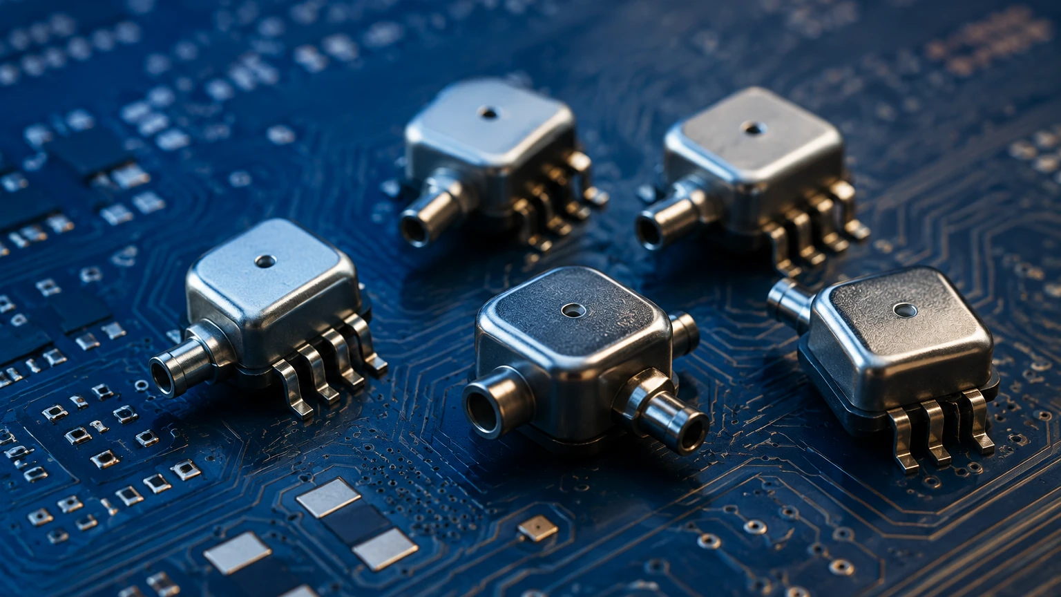
1. Electronic SMT (Surface Mount Technology): These are tiny, PCB-mounted components used inside control boxes or handheld devices. They are designed for clean, dry air and low-pressure ranges.
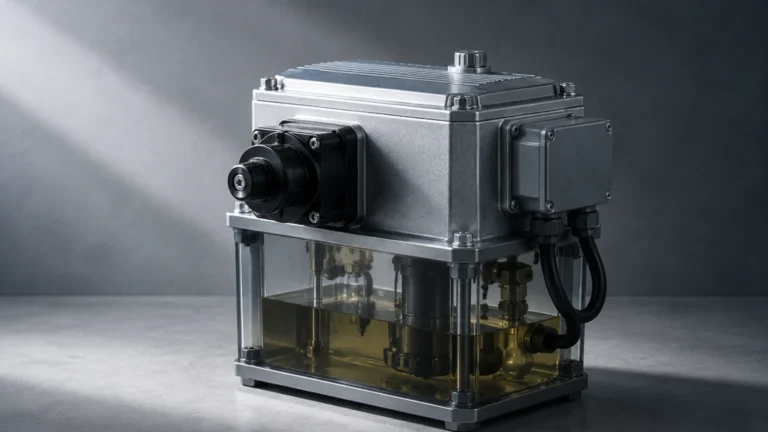
2. Industrial Flush Mount (Surface Integrated): This refers to sensors where the sensing diaphragm is flush with the process connection. Unlike traditional sensors that have a small internal cavity (which can clog), the surface-mount diaphragm is directly exposed to the process media. This is the primary focus for industrial level and process applications.
3. Key Evaluation and Selection Criteria
Choosing the right surface mount pressure sensor requires a comprehensive evaluation of the process environment. Failure to account for chemical compatibility or temperature fluctuations can lead to premature sensor failure or inaccurate data.
3.1 Pressure Range and Overpressure Rating
The nominal range should be selected so that the typical operating pressure falls within 50% to 75% of the sensor’s full scale. However, the "overpressure rating" is equally vital. In systems prone to water hammer or pump surges, a sensor must be able to withstand transient pressure spikes without losing calibration or rupturing the diaphragm.
3.2 Media Compatibility
The wetted parts—those in direct contact with the fluid—must be chemically compatible. While 316L stainless steel is standard, aggressive chemicals may require Hastelloy, Monel, or Tantalum coatings. For ceramic capacitive sensors, the O-ring material (FKM, EPDM, or FFKM) is often the limiting factor in chemical resistance.
3.3 Temperature Compensation
Pressure sensors are sensitive to temperature changes, which can cause the diaphragm material to expand or contract, leading to "zero drift." High-quality industrial sensors include internal temperature compensation circuits to maintain accuracy across a specified range (e.g., -20°C to +80°C).
3.4 Output Protocols
In modern industrial automation, the output signal determines how easily the sensor integrates into a PLC (Programmable Logic Controller) or SCADA system. Common options include:
* Analog: 4-20mA (current loop) is the industry standard due to its noise immunity over long distances.
* Digital: HART, Modbus RTU (RS485), and Profibus allow for remote diagnostics and multi-parameter reporting.
4. Practical Selection Table
The following table provides a quick reference for matching sensor types to common industrial applications.
| Application | Recommended Sensor Type | Key Advantage |
| :— | :— | :— |
| Clean Water Storage | Piezoresistive (Stainless Steel) | Cost-effective, high precision. |
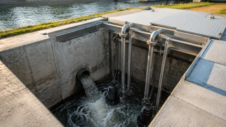
| Wastewater / Slurries | Flush Diaphragm (Surface Mount) | Prevents clogging from solids. |
| Chemical Processing | Ceramic Capacitive | High corrosion resistance. |
| Hygienic (Food/Pharma) | Flush Mount 316L / Electropolished | No dead space for bacteria growth. |
| Deep Well Level | Submersible Hydrostatic | Integrated cable venting for atmospheric ref. |
5. Installation Considerations and Best Practices
Correct installation is as important as sensor selection. Even the most accurate surface mount pressure sensor will provide faulty data if installed incorrectly.
5.1 Avoiding Air Traps
When installing a surface mount sensor in a pipe or tank, ensure the diaphragm is positioned to prevent air bubbles from becoming trapped against the sensing surface. In liquid applications, mounting the sensor at the side or bottom of the pipe is preferred over top-mounting.
5.2 Sealing and Torque
Over-tightening a threaded pressure sensor can introduce mechanical stress into the sensor housing, causing a shift in the zero-point calibration. Always follow the manufacturer’s torque specifications and use appropriate sealing materials (e.g., PTFE tape or bonded seals) that are compatible with the process media.
5.3 Atmospheric Venting
For gauge pressure sensors (which measure pressure relative to atmospheric pressure), the back of the diaphragm must be vented to the atmosphere. This is usually achieved through a small vent tube inside the signal cable. It is critical to ensure this vent tube is not kinked, blocked, or exposed to moisture, as this will cause significant measurement errors.
6. Common Risks and Limitations
While surface mount pressure sensors are highly versatile, engineers must remain aware of their limitations:
* Mechanical Damage: Flush diaphragms are exposed and can be easily dented or scratched during installation or cleaning. A damaged diaphragm usually requires a complete factory replacement.
* Vacuum Conditions: Not all sensors are designed to handle vacuum. If a tank is emptied rapidly without proper venting, a vacuum can form, potentially sucking the diaphragm outward and destroying the sensor.
* Signal Noise: In environments with heavy machinery or VFDs (Variable Frequency Drives), electromagnetic interference (EMI) can degrade analog signals. Using shielded cables and proper grounding is mandatory.
7. Maintenance and Troubleshooting
A proactive maintenance schedule ensures the longevity of the instrument. For surface mount sensors in viscous or "sticky" media, periodic inspection of the diaphragm is necessary to ensure no build-up has occurred.
Troubleshooting Steps:
1. Erratic Readings: Check for moisture in the vent tube or loose electrical connections.
2. Constant Full-Scale Output: This often indicates a broken diaphragm or a short circuit in the wiring.
3. Zero Drift: If the sensor reads a non-zero value when the tank is empty, it may require a "zero-point adjustment" via the internal potentiometer or digital interface.
8. Frequently Asked Questions (FAQ)
Q: Can a surface mount pressure sensor be used for steam applications?
A: Standard sensors cannot handle the high temperatures of live steam. A cooling element, such as a syphon or a capillary-mounted diaphragm seal, must be used to protect the sensing element.
Q: What is the difference between Gauge Pressure and Absolute Pressure?
A: Gauge pressure is measured relative to local atmospheric pressure (reading zero when vented). Absolute pressure is measured relative to a perfect vacuum. Most level applications use gauge pressure.
Q: How often should these sensors be calibrated?
A: In most industrial applications, an annual calibration check is standard. However, in critical chemical or safety-related processes, semi-annual calibration may be required.
Conclusion
Surface mount pressure sensors, particularly flush-mount industrial variants, provide a robust solution for level and pressure monitoring in challenging environments. By eliminating dead spaces and offering high compatibility with various media, they reduce maintenance requirements and improve process uptime. When planning an installation, engineers should confirm the chemical compatibility, pressure ranges, and required output protocols with their equipment provider. For a comprehensive look at available measurement technologies and technical support, professionals are encouraged to visit the Main Page of their preferred instrumentation partner to ensure the selected hardware meets the specific demands of their industrial application.