Rust Automation & Controls
Rust Automation & Controls
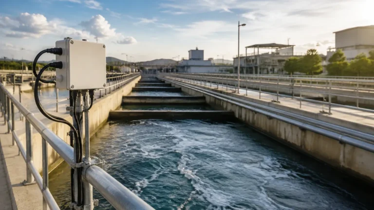
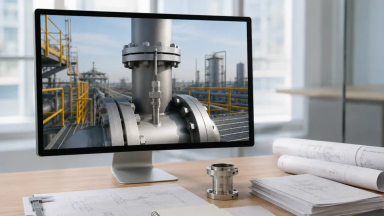
In the modern industrial landscape, the integration of precise level measurement with sophisticated control systems is essential for operational efficiency, safety, and environmental compliance. Whether managing water treatment facilities, chemical processing plants, or oil and gas refineries, the synergy between hardware sensors and the broader framework of rust automation & controls determines the reliability of the entire process loop. This guide explores the fundamental principles of level measurement, the selection criteria for automated systems, and the practical engineering considerations for implementing these technologies in demanding industrial environments.
The Role of Automation in Industrial Level Measurement
Automation in level measurement refers to the transition from manual tank gauging to continuous, real-time data acquisition and response. A robust control system relies on accurate input from field instruments to execute logic commands, such as starting a pump, closing a valve, or triggering an emergency shutdown.
In the context of rust automation & controls, the focus is often on ensuring that the hardware—the level meters and transmitters—can withstand corrosive environments while providing the digital or analog signals necessary for a PLC (Programmable Logic Controller) or DCS (Distributed Control System) to function. Without accurate level data, automation is impossible, leading to risks such as tank overfills, pump cavitation, or process downtime.
Core Principles of Level Measurement Technologies
Before selecting a control strategy, engineers must understand the physical principles governing different measurement technologies. Each method has specific strengths and limitations based on the media properties and tank conditions.
Radar Level Measurement (Non-Contact)
Radar level meters operate on the Time-of-Flight (ToF) principle. The instrument emits high-frequency microwave pulses (typically in the 26 GHz or 80 GHz range) toward the material surface. These pulses are reflected back to the sensor. The distance is calculated based on the time interval between emission and reception:
$$D = \frac{c \times t}{2}$$
Where $D$ is the distance, $c$ is the speed of light, and $t$ is the travel time. Radar is highly valued in automated systems because it is independent of changes in density, temperature, or pressure. For those seeking advanced instrumentation, you can Review product options and application support to see how modern radar units integrate with digital control protocols.
Ultrasonic Level Measurement
Similar to radar, ultrasonic sensors use ToF but rely on sound waves rather than electromagnetic waves. A transducer emits an ultrasonic pulse that bounces off the liquid surface. The speed of sound is affected by air temperature, so these sensors usually include integrated temperature compensation. Ultrasonic sensors are cost-effective solutions for water and wastewater applications but are limited in high-pressure or vacuum environments where sound cannot travel effectively.
Hydrostatic Level Measurement
Hydrostatic transmitters measure the pressure exerted by a liquid column at a specific point. The relationship is defined by the formula:
$$P = \rho \times g \times h$$
Where $P$ is pressure, $\rho$ is the liquid density, $g$ is gravity, and $h$ is the height of the liquid. In automated controls, hydrostatic sensors are often used in vented tanks or deep wells. They provide a direct electronic signal proportional to the level, making them easy to integrate into 4-20mA control loops.
Magnetic Level Gauges and Switches
Magnetic level gauges utilize a float containing a permanent magnet that moves with the liquid level inside a bypass chamber. Outside the chamber, a magnetic flap display or a reed-switch transmitter tracks the float's position. This technology provides both a local visual indication and a remote signal for automation, offering a fail-safe mechanical backup to electronic systems.
Integrating Level Sensors into Automation Control Systems
The "controls" aspect of rust automation & controls involves the communication between the field instrument and the control room. Modern level meters support various output protocols that facilitate this integration:
1. 4-20mA HART: The industry standard for analog signaling. The 4-20mA loop provides the primary variable (level), while the HART (Highway Addressable Remote Transducer) protocol allows for digital configuration and diagnostics over the same wires.
2. Modbus RTU/TCP: A common protocol for connecting sensors directly to PLCs or SCADA systems, allowing for the transmission of multiple parameters (level, temperature, signal strength) over a single bus.
3. Profibus/Foundation Fieldbus: Used in complex plant architectures where high-speed, multi-device communication is required.
Automation systems use these signals to perform PID (Proportional-Integral-Derivative) control. For example, if a chemical tank level drops below a setpoint, the control system increases the inflow rate by modulating a control valve, ensuring a steady state in the production line.
Selecting the Right Instrument for Industrial Environments
Choosing the correct technology is critical for the longevity of the automation system. Engineers must evaluate the chemical compatibility of the wetted parts to prevent rust and corrosion, which can lead to sensor failure.
Selection Criteria Table
| Technology | Typical Accuracy | Max Range | Media Compatibility | Best Use Case |
| :— | :— | :— | :— | :— |
| 80GHz Radar | ±1 mm | 120 m | Corrosive liquids, solids, dust | High-precision chemical storage |
| Ultrasonic | ±0.25% of range | 15 m | Water, wastewater, acids | Open channel flow, sumps |
| Hydrostatic | ±0.1% to 0.5% | 200 m | Clean liquids, oils | Deep wells, vented tanks |
| Magnetic Gauge | ±5 mm | 6 m | High pressure, high temp | Boiler drums, oil separators |
| Level Switch | N/A (Point) | N/A | Liquids or solids | Overfill protection, pump dry-run |

Installation Considerations for Automated Systems
Proper installation is the bridge between a theoretical design and a functional automation loop. Even the most advanced rust automation & controls setup will fail if the primary sensor is poorly positioned.
* Blocking Distance (Dead Zone): Every non-contact sensor (radar/ultrasonic) has a minimum distance near the face of the transducer where it cannot measure. Ensure the maximum high-level setpoint in the control system does not enter this zone.
* Internal Obstructions: Agitators, ladders, and heating coils can create false echoes. Modern radar meters offer "false echo suppression" software, but physical clearance is always preferred. For ultrasonic sensors, the beam angle (typically 5° to 10°) must be kept clear of the tank wall.
* Stilling Wells: In turbulent tanks or those with heavy foam, installing the sensor inside a stilling well (a vertical pipe) can stabilize the surface and provide a cleaner signal for the control system.
* Environmental Protection: In outdoor installations, sunshields should be used to prevent temperature-induced errors in ultrasonic sensors and to protect the electronics of radar units from extreme thermal cycling.
Limitations and Challenges
While automation significantly improves process reliability, it is not without challenges. Engineers must account for the following limitations:
1. Vapor and Condensation: Heavy steam or chemical vapors can attenuate ultrasonic signals. Radar is generally immune to vapor but can be affected by heavy condensation on the antenna lens if not equipped with a PTFE dropper or purging system.
2. Dielectric Constant ($DK$ value): Radar relies on the reflectivity of the material. Materials with very low $DK$ values (like certain oils or liquefied gases) reflect less energy, requiring high-sensitivity antennas or guided wave radar (GWR).
3. Material Build-up: In sticky or viscous media, material can accumulate on the sensor face. Automated systems should include diagnostic alarms to alert operators when signal strength degrades due to coating.
Troubleshooting and Maintenance in Automated Level Control
A proactive maintenance schedule ensures that the automation and controls remain accurate over time.
* Calibration Verification: Periodically compare the electronic output to a physical measurement (dip tape). Many smart transmitters allow for "dry calibration" via software, but a wet calibration is the gold standard for critical loops.
* Signal Integrity: Check for electromagnetic interference (EMI) if the signal is erratic. Ensure that shielded cables are used and properly grounded at the control cabinet side.
* Corrosion Inspection: Regularly inspect mounting flanges and housings for signs of rust. Utilizing 316L stainless steel or plastic-coated housings is a standard practice in rust-prone environments to protect the internal circuitry.
Frequently Asked Questions
Q: How does 80 GHz radar differ from 26 GHz radar in an automated system?
A: 80 GHz radar has a much narrower beam angle and a shorter wavelength. This allows it to ignore internal tank obstructions more effectively and measure through smaller nozzles, providing a more reliable signal for the control system in complex tank geometries.
Q: Can ultrasonic sensors be used for rust-prone chemical tanks?
A: Yes, provided the sensor body is made of corrosion-resistant materials like PVDF or PTFE. However, if the chemical produces heavy vapors, radar is often a more reliable choice for automation.
Q: What is the benefit of a redundant level system?
A: In high-risk applications, using two different technologies (e.g., a radar meter and a magnetic level switch) prevents common-mode failures. The control system can compare the two signals and trigger an alarm if they diverge, significantly increasing the safety integrity level (SIL) of the plant.
Q: How do I handle level measurement in tanks with heavy foam?
A: Foam can absorb ultrasonic and radar signals. For automated control in foaming conditions, hydrostatic transmitters or guided wave radar (where the pulse travels along a probe) are typically recommended as they are less affected by surface conditions.
By understanding these technical nuances and selecting the appropriate hardware, engineers can build robust systems that integrate seamlessly with rust automation & controls frameworks. For further technical specifications and to explore a wide range of industrial instruments, users are encouraged to Review product options and application support to find the ideal solution for their specific process requirements.