Non Guided Wave Radar Level Transmitter
Non Guided Wave Radar Level Transmitter: A Comprehensive Engineering Guide
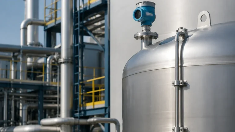
In the field of industrial process automation, accurate level measurement is critical for inventory management, process safety, and operational efficiency. The non guided wave radar level transmitter has emerged as a primary solution for non-contact level measurement in demanding environments. Unlike contact-based technologies, these instruments emit electromagnetic pulses that travel through the headspace of a vessel, reflecting off the material surface without physical interaction with the medium. This guide examines the technical principles, selection criteria, and installation requirements for implementing non-guided radar technology in industrial settings.
Understanding the Non Guided Wave Radar Level Transmitter
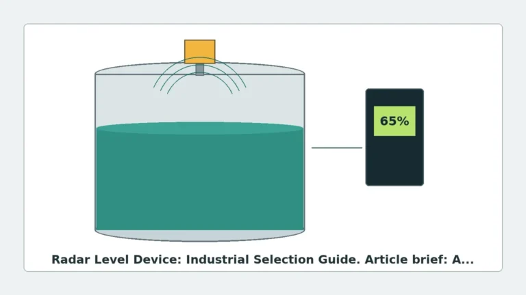
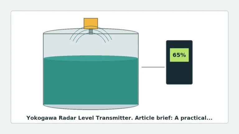
A non guided wave radar level transmitter (often referred to as non-contact radar) operates on the principle of microwave propagation. Because microwaves do not require a physical medium or a waveguide to travel, they are ideal for applications where the process media is corrosive, viscous, or prone to coating.
In contrast to Guided Wave Radar (GWR), which uses a probe to direct the signal, non-guided radar transmits signals through the air via an antenna. This design eliminates the risk of probe damage from mechanical stress in agitated tanks and simplifies maintenance, as the sensor is typically located at the top of the vessel, away from the product.
Core Measurement Principles: Pulse vs. FMCW
Modern Radar Level Meters generally utilize one of two primary measurement techniques: Pulse Radar or Frequency Modulated Continuous Wave (FMCW).
1. Pulse Radar (Time of Flight)
Pulse radar transmitters emit a short microwave signal and measure the time it takes for the pulse to travel to the surface and return to the receiver. This is known as Time of Flight (ToF). The distance is calculated using the formula:
Distance = (Speed of Light × Travel Time) / 2
Pulse radar is known for its energy efficiency and is often used in battery-powered or loop-powered applications. However, it may require more sophisticated signal processing to filter out noise in complex environments.
2. Frequency Modulated Continuous Wave (FMCW)
FMCW technology transmits a continuous signal with a constantly changing frequency. When the reflected signal is received, it is compared to the signal being transmitted at that exact moment. The frequency difference (beat frequency) is directly proportional to the distance. FMCW is generally considered more accurate and provides a better signal-to-noise ratio, making it the preferred choice for high-precision industrial applications and environments with vapor or dust.
Antenna Selection and Beam Angle Considerations
The antenna is the interface between the transmitter electronics and the process. The choice of antenna determines the beam angle and the instrument's ability to handle specific process conditions.
* Horn Antennas: These are the most common for 26GHz systems. They are robust and suitable for large tanks. Larger horn diameters result in narrower beam angles, which help avoid internal obstructions like agitators or heating coils.
* Lens Antennas: Typically used in high-frequency 80GHz transmitters. The lens allows for a very narrow beam (often as small as 3°) from a compact process connection. This is ideal for tall, narrow silos or vessels with many internal structures.
* Parabolic Antennas: Used for very long-range measurements (up to 100 meters) or for materials with very low dielectric constants, as they provide high gain.
Beam Angle and "Blind Zones"
The beam angle is defined as the angle where the power density is half of the maximum power. A narrower beam angle is almost always preferable in industrial engineering because it minimizes "false echoes" from tank walls and internal hardware. Additionally, every radar transmitter has a "near-zone" or "blind zone" (typically 50mm to 200mm from the antenna) where measurement is not possible.
Engineering Selection Criteria for Process Industries
Selecting the correct non guided wave radar level transmitter requires a detailed analysis of the process environment. The following table provides a general selection framework for common industrial scenarios.
Selection Reference Table
| Process Condition | Recommended Frequency | Antenna Type | Consideration |
| :— | :— | :— | :— |
| Large Storage Tanks (Liquids) | 26 GHz | Horn | Cost-effective, reliable for large surfaces. |
| Narrow Silos (Solids/Dust) | 80 GHz | Lens | Narrow beam avoids wall interference. |
| Corrosive Chemicals | 26/80 GHz | PTFE Flange/Drop | Requires chemical-resistant wetted parts. |
| High Temperature/Pressure | 26 GHz | Ceramic Seal | Specialized seals prevent leakage and damage. |
| Agitated Vessels | 80 GHz | Lens | High frequency handles surface turbulence better. |
| Low Dielectric ($\epsilon_r < 2$) | 80 GHz | Parabolic/Large Horn | Requires high sensitivity to detect weak reflections. |
The Role of the Dielectric Constant (εr)
The dielectric constant of the medium is the most critical factor in radar measurement. It determines how much of the microwave energy is reflected back to the sensor.
* High εr (e.g., Water, εr ≈ 80): Excellent reflection, very easy to measure.
* Low εr (e.g., Oil, Hydrocarbons, εr ≈ 2): Weak reflection; requires a sensitive transmitter and potentially a larger antenna to capture enough signal.

Installation Best Practices and Constraints
To ensure the accuracy of a non guided wave radar level transmitter, engineers must adhere to strict installation guidelines. Failure to do so often results in signal loss or erratic readings.
1. Nozzle Height and Diameter: The antenna should extend slightly beyond the bottom of the mounting nozzle to prevent the nozzle edge from creating a massive false reflection. If the nozzle is long, a specialized antenna extension should be used.
2. Positioning: The transmitter should generally be installed at 1/4 to 1/6 of the tank diameter from the wall. Mounting it too close to the wall causes interference, while mounting it in the exact center can lead to multiple-path reflections in domed-roof tanks.
3. Obstruction Clearance: Ensure the "signal cone" (based on the beam angle) is clear of ladders, pipes, and agitator blades. If an obstruction is unavoidable, most modern transmitters offer a "False Echo Suppression" or "Background Subtraction" feature to digitally ignore these fixed reflections.
4. Orientation: For solid materials, the transmitter may need an aiming flange (swivel mount) to align the beam with the angle of repose of the material.
Limitations and Application Risks
While highly versatile, non-guided radar is not a universal solution. Engineers must be aware of the following limitations:
* Heavy Foam: Dense, thick foam can absorb the microwave signal entirely, leading to a "Loss of Echo" (LOE) error. In such cases, a guided wave radar or a low-frequency non-contact radar may be more effective.
* Extreme Dust: While 80GHz radar penetrates dust better than ultrasonic sensors, extremely heavy dust concentrations during pneumatic filling can attenuate the signal.
* Vacuum Conditions: While microwaves travel fine in a vacuum, the physical seal of the transmitter must be rated for the pressure differential to prevent instrument failure.
* Multiple Interfaces: Non-guided radar is generally not suitable for measuring the interface between two liquids (e.g., oil over water). Guided wave radar is the standard for interface applications.
Information for International Procurement
When sourcing a non guided wave radar level transmitter for global projects, buyers and engineers should confirm the following technical specifications with the manufacturer:
1. Frequency Band: Confirm if 26GHz or 80GHz is better suited for the specific vessel geometry.
2. Process Connection: Specify Flange (ANSI/DIN) or Threaded (NPT/G) standards and material (316L, PTFE, etc.).
3. Output Protocol: Ensure compatibility with the control system (4-20mA HART, Modbus RS485, or Profibus).
4. Certifications: Verify requirements for Explosion-proof (Ex d), Intrinsically Safe (Ex ia), or SIL2/3 functional safety ratings.
Frequently Asked Questions (FAQ)
Q: Can non-guided radar measure through a plastic tank roof?
A: Yes, if the roof is made of a non-conductive material like polyethylene or fiberglass and is not too thick, the radar signal can pass through it, allowing for measurement without a tank opening.
Q: How does 80GHz technology compare to 26GHz?
A: 80GHz offers a much narrower beam and smaller antenna size, making it superior for narrow tanks and avoiding obstructions. 26GHz is often more robust in the presence of heavy steam or certain types of foam.
Q: Does the pressure inside the tank affect the measurement?
A: No. Unlike ultrasonic sensors, which depend on the speed of sound (which changes with air density), radar uses electromagnetic waves. The speed of light is constant regardless of pressure or temperature, making radar much more stable in high-pressure reactors.
Q: What maintenance is required for these transmitters?
A: Because there are no moving parts and no contact with the medium, maintenance is minimal. Periodic inspection of the antenna for heavy buildup or condensation is recommended, though many units feature a "self-cleaning" lens design or air purge connections to mitigate this.
By understanding these technical parameters, industrial engineers can successfully deploy non-guided radar technology to achieve reliable, long-term level monitoring in even the most challenging process environments.