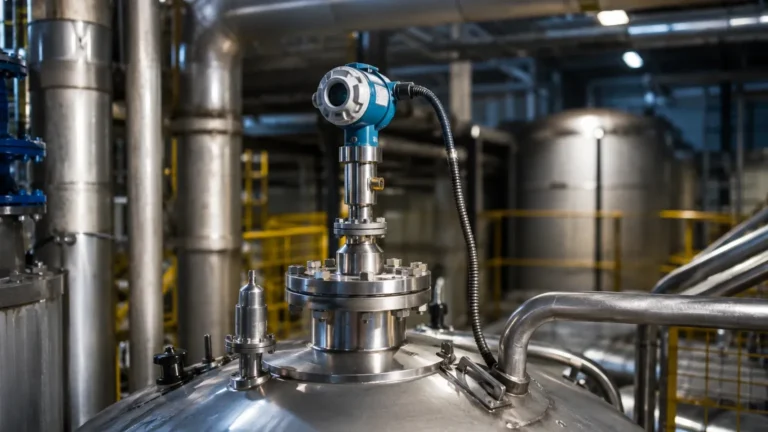
Non Contact Radar Level Transmitter Installation
Non Contact Radar Level Transmitter Installation: A Comprehensive Engineering Guide
In the landscape of industrial automation, precise level measurement is critical for operational efficiency, safety, and inventory management. Among the various technologies available, Radar Level Meters have emerged as a preferred solution for challenging environments. Specifically, non-contact radar technology offers the advantage of measuring liquid or solid levels without physical contact with the medium, reducing maintenance requirements and extending instrument lifespan. However, the accuracy of these instruments is heavily dependent on proper non contact radar level transmitter installation and the understanding of electromagnetic wave propagation within a vessel.
Understanding the Measurement Principles
Before proceeding with installation, engineers must understand how non-contact radar transmitters function. These devices utilize electromagnetic waves, typically in the microwave spectrum, to determine the distance from the sensor to the material surface.
Pulse Radar vs. FMCW
There are two primary methods used in industrial radar level measurement:
1. Pulse Radar (Time-of-Flight): The instrument emits a short microwave pulse that travels at the speed of light. It hits the surface of the medium, reflects back, and is received by the antenna. The distance is calculated using the formula: $D = (c \times t) / 2$, where $c$ is the speed of light and $t$ is the transit time.
2. FMCW (Frequency Modulated Continuous Wave): The transmitter emits a continuous signal with a constantly changing frequency. The frequency difference between the emitted signal and the reflected signal is proportional to the distance. FMCW is generally more accurate and provides better signal-to-noise ratios, making it ideal for complex applications with turbulence or vapor.
The Role of Dielectric Constant (εr)
The reflection of the radar signal depends on the dielectric constant of the medium. Materials with high dielectric constants (like water, $\varepsilon_r \approx 80$) reflect signals strongly. Materials with low dielectric constants (like hydrocarbons or dry powders, $\varepsilon_r < 2$) reflect very little energy, requiring more sensitive electronics and specialized antenna configurations.
Selection Criteria for Radar Level Meters
Choosing the right instrument is the first step toward a successful non contact radar level transmitter installation. The selection depends on the frequency, antenna type, and process conditions.
Frequency Considerations
* 6.3 GHz (C-Band): Best for applications with heavy foam, steam, or extreme turbulence. The longer wavelength is less affected by surface disturbances but requires larger antennas.
* 26 GHz (K-Band): The industry standard for most liquid applications. It offers a balance between beam angle and signal strength.
* 80 GHz (W-Band): Features a very narrow beam angle (often less than 3°). This is ideal for tall, narrow tanks or vessels with internal obstructions like agitators and heating coils.
Antenna Types
* Horn Antenna: Standard for most tanks; available in various diameters to control beam width.
* Lens Antenna: Typically used in 80 GHz units; flush-mounted and resistant to condensation or buildup.
* Parabolic Antenna: Used for long-range measurements in large silos or for materials with very low reflectivity.
| Feature | 26 GHz Radar | 80 GHz Radar |
| :— | :— | :— |
| Beam Angle | 8° to 20° | 3° to 6° |
| Accuracy | ±3 mm to ±5 mm | ±1 mm |
| Max Range | Up to 30 m | Up to 120 m |
| Best Use Case | General process tanks | Narrow silos, agitators |
| Vapor Resistance | Moderate | High |
Non Contact Radar Level Transmitter Installation Guidelines
Proper physical placement is the most significant factor in ensuring reliable measurement. Even the most advanced radar level meters will fail if installed in a position where internal reflections overwhelm the signal from the product surface.
1. Mounting Position Relative to Tank Walls
The transmitter should not be mounted in the exact center of a tank (especially those with domed roofs) nor too close to the tank wall.
* The 1/6 Rule: A general rule of thumb is to install the sensor at a distance of 1/6 of the tank diameter from the side wall.
* Wall Interference: If the sensor is too close to the wall (less than 200 mm), the beam may interact with the wall surface or welds, causing parasitic echoes.
* Center Mounting: Mounting in the center of a domed tank can cause "multiple echoes" where the signal bounces off the curved roof and creates a false high-level reading.
2. Nozzle Geometry and Height
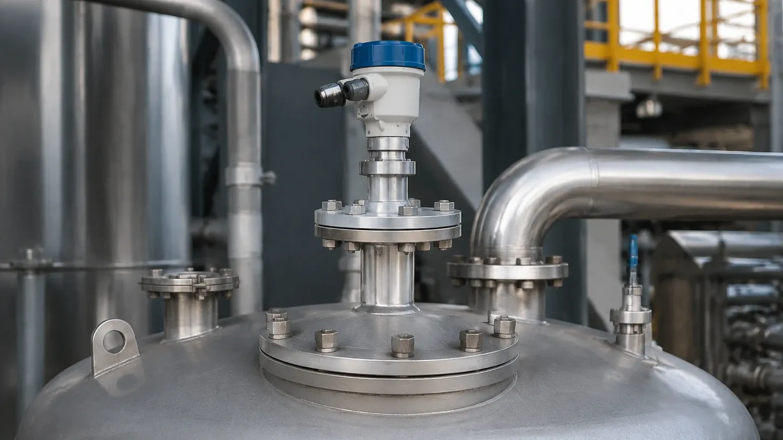
The nozzle is the pipe section where the radar is mounted. For non-contact radar, the antenna should ideally extend beyond the bottom of the nozzle.
* Nozzle Diameter: Ensure the nozzle diameter is larger than the antenna diameter.
* Nozzle Height: If the nozzle is very long, the radar signal may reflect off the internal walls of the pipe before reaching the tank. If a long nozzle is unavoidable, a 80 GHz radar with a narrow beam is required to prevent interference.
3. Avoiding Internal Obstructions
The "signal cone" or beam width must be kept clear of any metallic or non-metallic obstructions. Common obstructions include:
* Inlet pipes and filling streams.
* Ladders and reinforcement struts.
* Agitators (mixers).
* Heating coils.
If an obstruction is unavoidable, many modern Radar Level Meters allow for "False Echo Suppression" or "Echo Mapping," where the software learns to ignore static reflections from fixed objects.
4. Orientation and Alignment
* Vertical Alignment: The antenna must be installed perpendicular to the product surface. For liquids, this means perfectly vertical. For solids, an adjustable flange (aiming kit) may be used to point the radar at the angle of repose of the material.
* Polarization: Radar waves are polarized. Rotating the sensor in its mounting can sometimes help minimize reflections from nearby walls or obstructions.
Application-Specific Installation Considerations
Liquids with Agitators
When measuring liquids in tanks with agitators, the turbulence and the blades themselves create significant noise. To mitigate this:
1. Install the radar as far from the agitator shaft as possible.
2. Use a high-frequency (80 GHz) unit to narrow the beam.
3. Enable software filtering to smooth out the fluctuations caused by surface ripples.
Solids and Powders
Measuring solids involves challenges like dust and uneven surfaces.
* Dust: While radar penetrates dust better than ultrasonic sensors, heavy dust can still attenuate the signal. High-power 26 GHz or 80 GHz units are recommended.
* Angle of Repose: Solids do not sit flat. The radar should be aimed at the middle of the slope to get a representative average level.
High Temperature and Pressure
In chemical or oil and gas applications, process temperatures can exceed 200°C and pressures can surpass 40 bar.
* Thermal Isolation: Use a standoff pipe or a cooling extension to protect the transmitter electronics from heat.
* Sealing: Ensure the process seal (typically PTFE or PEEK) is compatible with the chemical properties of the medium.
Limitations of Non-Contact Radar
While highly versatile, non-contact radar has limitations that must be addressed during the engineering phase:
1. Minimum Dielectric Constant: If the $\varepsilon_r$ is below 1.4, the signal reflection might be too weak for standard non-contact radar. In such cases, a stilling well or guided wave radar may be necessary.
2. Heavy Foam: Extremely dense, thick foam (like shaving cream) can absorb the radar signal entirely. While low-frequency radar (6 GHz) can penetrate some foam, it is not a universal solution.
3. The Dead Zone (Blocking Distance): Every radar has a minimum distance (usually 50 mm to 200 mm from the antenna) where it cannot measure accurately. This must be factored into the tank's overfill protection logic.
Maintenance and Troubleshooting
Non-contact radar is generally low-maintenance because it has no moving parts. However, certain conditions require attention:
* Antenna Buildup: In sticky applications, material may accumulate on the antenna. While many radars can "see through" a thin layer of coating, heavy buildup will cause signal loss. Use a lens antenna with a flat face or a purging connection (compressed air) to keep the antenna clean.
* Condensation: Water droplets on the antenna can refract the signal. PTFE-coated antennas or lens antennas are designed to shed droplets effectively.
Common Troubleshooting Steps
* Signal Loss: Check for antenna coating or a change in the dielectric constant of the medium.
* Inaccurate Reading at High Levels: Check if the product has entered the dead zone or if there is interference from the mounting nozzle.
* Fluctuating Readings: Increase the damping (integration time) in the sensor settings to average out surface turbulence.
Frequently Asked Questions (FAQ)
Q: Can I install a radar level meter on a plastic tank?
A: Yes. Radar waves can penetrate plastic. It is possible to mount the radar outside the tank, beaming through the plastic roof, provided the plastic is not carbon-filled or metallic-lined. However, signal strength will be reduced.
Q: How do I handle a tank with a spherical bottom?
A: When the tank is nearly empty, the spherical bottom can act as a lens, focusing the radar signal away from the antenna. In these cases, the radar might lose the signal at the very bottom. This can be corrected by using a stilling well or adjusting the low-level offset in the software.
Q: Does the pressure inside the tank affect the speed of the radar wave?
A: No. Unlike ultrasonic waves, which depend on air density and temperature, radar waves (electromagnetic) are virtually unaffected by pressure or vacuum. This makes them ideal for high-pressure reactors.
Q: What is the maximum distance a non-contact radar can measure?
A: Modern long-range units, particularly those used in large grain silos or water reservoirs, can measure distances up to 120 meters (approx. 393 feet).
Conclusion
Successful non contact radar level transmitter installation requires a synergy between high-quality instrumentation and sound engineering practices. By selecting the appropriate frequency, respecting the geometry of the vessel, and accounting for the physical properties of the medium, operators can achieve reliable, maintenance-free level measurement. For complex applications involving corrosive chemicals or extreme temperatures, consulting with a professional manufacturer like Welk ensures that the selected Radar Level Meters are optimized for the specific process environment, providing long-term accuracy and safety.
Download Non Contact Radar Level Transmitter Installation as a PDF