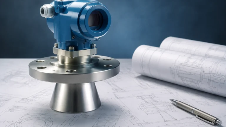
Standard Gauging System
Standard Gauging System
In industrial process control and inventory management, a standard gauging system serves as the foundational infrastructure for monitoring liquid levels, volumes, and masses within storage tanks and process vessels. These systems are not merely individual sensors but integrated solutions designed to provide repeatable, accurate data for applications ranging from water treatment and chemical processing to high-stakes oil and gas custody transfer. For engineers and facility managers, selecting the correct standard gauging system requires a deep understanding of measurement physics, environmental constraints, and the specific requirements of the media being measured.
At its core, a standard gauging system utilizes various sensing technologies—such as radar, ultrasonic, hydrostatic, or magnetic—to convert physical levels into electrical signals. These signals are then processed and transmitted to a central control system or local display. As a professional manufacturer, Welk provides these high-precision instruments to ensure that industrial automation remains reliable and cost-effective across global markets.
Measurement Principles in Gauging Systems
Before selecting a system, it is essential to understand the underlying physical principles that govern how level measurement instruments interact with the process media. Most modern systems fall into two categories: non-contact and contact measurement.
Non-Contact Measurement: Radar and Ultrasonic
Non-contact technologies are often preferred in a standard gauging system when the media is corrosive, viscous, or prone to coating instruments.
1. Radar Level Measurement (ToF): Radar level meters emit high-frequency electromagnetic pulses (typically in the GHz range). These pulses travel at the speed of light, reflect off the surface of the liquid, and return to the sensor. The system calculates the distance based on the Time-of-Flight (ToF). Radar is highly effective because it is largely unaffected by temperature fluctuations, pressure changes, or the presence of vapors and dust.
2. Ultrasonic Level Measurement: Similar to radar, ultrasonic sensors use ToF but rely on sound waves rather than electromagnetic waves. A transducer emits an ultrasonic pulse that bounces off the liquid surface. While cost-effective for water treatment and open-channel flow, ultrasonic waves are sensitive to air temperature changes and can be attenuated by heavy foam or vacuum conditions.
Contact Measurement: Hydrostatic and Magnetic
Contact-based systems are robust and often used where the physical properties of the liquid are well-defined.
1. Hydrostatic Level Transmitters: This principle relies on the relationship between the height of a liquid column and the pressure it exerts at the base of the tank. The formula $P = \rho \cdot g \cdot h$ (where $P$ is pressure, $\rho$ is density, $g$ is gravity, and $h$ is height) allows the transmitter to calculate the level. These are widely used in deep wells and vented tanks.
2. Magnetic Level Gauges: These systems use a float containing a permanent magnet that moves with the liquid level inside a bypass chamber. Outside the chamber, a series of magnetic flags or a transmitter responds to the float's position. This provides a clear visual indication and a reliable electronic signal without the sensor directly touching the fluid electronics.
Selection Criteria for a Standard Gauging System
Choosing the right technology depends on the operational environment and the required precision. The following table provides a comparison of the primary technologies used in a standard gauging system.
Technology Comparison Table
| Feature | Radar (80GHz/26GHz) | Ultrasonic | Hydrostatic | Magnetic Gauge |
| :— | :— | :— | :— | :— |
| Accuracy | ±1 mm to ±3 mm | ±0.25% of range | ±0.1% to ±0.5% | ±5 mm (visual) |
| Media Type | Liquids, Solids, Slurries | Liquids, Coarse Solids | Clean Liquids | Liquids |
| Max Range | Up to 120 meters | Up to 30 meters | Up to 200 meters | Up to 15 meters |
| Pressure Limit | Up to 160 Bar | Atmospheric | Varies by sensor | Up to 320 Bar |
| Temperature | -40°C to +450°C | -40°C to +80°C | -20°C to +100°C | -196°C to +450°C |
| Contact | Non-contact | Non-contact | Contact | Contact (Float) |
When evaluating these options, engineers must prioritize the "Main Page" of their technical requirements: accuracy, reliability, and ease of integration. For more detailed specifications on these instruments, you can Review product options and application support to find the specific model that fits your process parameters.
Installation Considerations and Best Practices
Even the most advanced standard gauging system will fail to provide accurate data if installed incorrectly. Proper mechanical and electrical installation is critical to long-term performance.
Nozzle and Mounting Position
For radar and ultrasonic systems, the sensor should be mounted away from the tank wall to avoid false echoes. Ideally, the sensor should be positioned at 1/4 to 1/3 of the tank diameter from the wall. Ensure that the signal path is clear of internal obstructions such as ladders, heating coils, or agitators.
Dead Zones (Blocking Distance)
Every non-contact sensor has a "dead zone" or blocking distance—a region directly below the sensor where measurement is impossible. In a standard gauging system, the sensor must be mounted high enough so that the maximum liquid level never enters this zone. For ultrasonic sensors, this is typically 0.2 meters to 0.5 meters, while high-frequency radar has significantly smaller dead zones.
Stilling Wells and Bypass Chambers
In applications involving heavy turbulence or foam, using a stilling well (a vertical pipe inside the tank) or a bypass chamber (mounted externally) can stabilize the liquid surface. This allows the gauging system to provide a steady reading despite the chaotic conditions inside the main vessel.
Integration and Communication Protocols
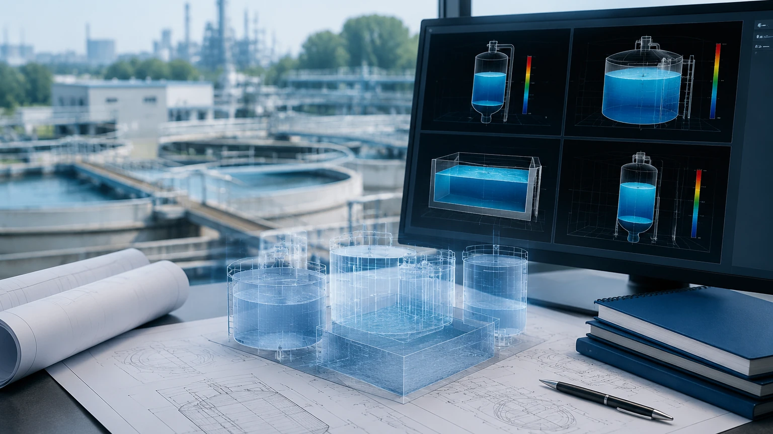
A modern standard gauging system is rarely a standalone unit. It must communicate with Distributed Control Systems (DCS), Programmable Logic Controllers (PLC), or SCADA systems. Common output options include:
* 4-20mA Analog Signal: The industry standard for simple level transmission.
* HART Protocol: Allows digital communication over the analog signal, enabling remote configuration and diagnostics.
* RS485/Modbus: Ideal for multi-drop installations where multiple sensors are connected to a single bus.
* Wireless Solutions: Increasingly used in remote tank farms where cabling costs are prohibitive.
Limitations and Common Risks
While a standard gauging system is designed for durability, certain factors can introduce errors or lead to equipment failure:
1. Vapor and Condensation: While radar handles vapor well, heavy condensation on an ultrasonic transducer face can block the signal. Welk offers specialized antenna designs to mitigate these effects.
2. Density Fluctuations: Hydrostatic systems are dependent on liquid density. If the temperature of the liquid changes significantly, the density changes, leading to an error in the level calculation unless temperature compensation is integrated.
3. Build-up and Scaling: In chemical or wastewater applications, material can build up on the sensor. Non-contact radar with a PTFE-enclosed antenna is often the best solution for these "sticky" environments.
4. Dielectric Constant: Radar systems rely on the dielectric constant ($ε_r$) of the media. Liquids with a very low dielectric constant (like certain oils or liquefied gases) reflect less energy, requiring high-sensitivity radar units.
Frequently Asked Questions (FAQ)
Q: How do I choose between 26GHz and 80GHz radar for my gauging system?
A: 80GHz radar offers a narrower beam angle and higher precision, making it ideal for small tanks or vessels with many internal obstructions. 26GHz radar is often more robust in applications with heavy dust or steam where a larger wavelength can better penetrate the atmosphere.
Q: Can a standard gauging system measure both level and interface?
A: Yes, certain technologies like Guided Wave Radar (GWR) are specifically designed to measure the interface between two liquids, such as oil and water, by detecting the different dielectric reflections from each layer.
Q: What maintenance is required for these systems?
A: Non-contact systems require very little maintenance beyond occasional cleaning of the antenna or transducer face. Contact systems like magnetic gauges should be checked periodically for sediment build-up in the chamber that might restrict float movement.
Q: Is it possible to use these systems in hazardous areas?
A: Absolutely. Most industrial level meters are available with Ex-proof (Explosion-proof) or Intrinsically Safe (IS) certifications, such as ATEX or IECEx, for use in flammable environments.
Conclusion
Implementing a robust standard gauging system is a critical step in optimizing industrial efficiency and safety. By understanding the physics of measurement—whether it be the electromagnetic precision of radar or the mechanical reliability of a magnetic gauge—engineers can select a solution that minimizes downtime and maximizes accuracy.
Welk continues to lead the industry by providing versatile, high-quality level measurement instruments tailored to the rigors of modern automation. For comprehensive technical data, installation manuals, and to explore our full range of products, please visit our Main Page to find the ideal level measurement solution for your specific application. Whether you are managing a local water treatment plant or a global chemical manufacturing facility, the right gauging system is the key to precise control.