How Does a Coriolis Meter Work
How Does a Coriolis Meter Work
In the realm of industrial process control, the ability to measure the mass of a moving fluid accurately is often more critical than measuring its volume. While many flowmeters calculate volume, the Coriolis meter stands out as a premier technology for direct mass flow measurement. Understanding how does a coriolis meter work requires a dive into the physics of motion, specifically the Coriolis effect, and how modern engineering harnesses this phenomenon to provide highly precise data for chemical, oil and gas, and water treatment applications.
As a leading manufacturer of industrial measurement instruments, Welk provides a range of solutions including radar and ultrasonic sensors. While these are primary for level measurement, the Coriolis meter serves as a vital component in the broader automation ecosystem. For more information on integrated measurement solutions, you can visit our Main Page.
The Fundamental Principle: The Coriolis Effect
The Coriolis effect is an inertial force first described by the French mathematician Gaspard-Gustave de Coriolis in 1835. It explains the apparent deflection of an object moving within a rotating frame of reference. In an industrial Coriolis meter, this "rotation" is simulated by vibrating the internal flow tubes at their natural resonant frequency.
The Analogy of the Seesaw
To visualize how does a coriolis meter work, imagine a person walking from the center of a rotating merry-go-round toward the edge. As they move outward, their tangential velocity increases, causing them to feel a force pushing against the direction of rotation. Conversely, moving toward the center causes a force in the opposite direction.
In a flowmeter, the fluid represents the person, and the vibrating tube represents the rotating platform. As fluid enters the vibrating tube, it is forced to take on the vertical velocity of the vibration. As it moves toward the peak of the vibration (the "center"), and then away from it, the fluid resists this change in momentum, exerting a force back onto the tube wall.
Internal Components and Mechanics
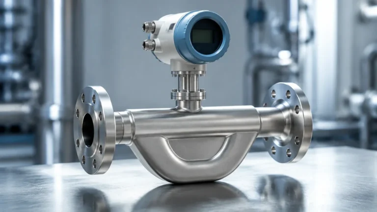
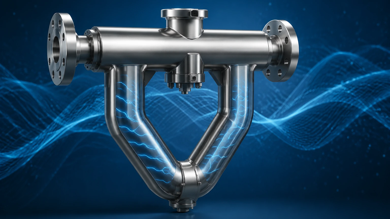
A standard Coriolis meter consists of two primary parts: the sensor (the wetted part) and the transmitter (the electronics). Inside the sensor housing, you will typically find:
1. Flow Tubes: These are usually one or two tubes, often shaped like a "U" or a triangle, though straight-tube designs exist for specific sanitary or low-pressure-drop applications.
2. Drive Coil: This electromagnetic component induces the vibration in the tubes, usually at a frequency between 50 and 150 Hz.
3. Pick-off Sensors: Located at the inlet and outlet sides of the tube, these electromagnetic sensors detect the motion of the tubes.
4. Temperature Sensor: Usually a PT100 or similar RTD, used to compensate for changes in tube elasticity caused by temperature fluctuations.
Measuring Mass Flow: The Phase Shift
The core answer to how does a coriolis meter work lies in the concept of "phase shift."
When there is no flow, the drive coil vibrates the tubes in a uniform, symmetrical manner. The pick-off sensors at the inlet and outlet detect the same sine wave motion at the same time. They are "in phase."
As soon as fluid begins to flow through the tubes, the Coriolis effect takes hold. The fluid entering the meter resists being pushed upward by the vibration, causing the inlet side of the tube to lag behind the vibration of the drive coil. As the fluid reaches the outlet side, it has already gained momentum and resists being slowed down, causing the outlet side of the tube to lead the vibration.
This results in a twisting motion of the tube. The time difference between the sine waves detected by the two pick-off sensors is known as the phase shift (Δt). This phase shift is directly proportional to the mass flow rate of the fluid. Because this measurement relies on mass and inertia, it is independent of the fluid's viscosity, conductivity, or flow profile.
Measuring Density: Resonant Frequency
Beyond mass flow, Coriolis meters are exceptional density meters. This is achieved by monitoring the resonant frequency of the vibrating tubes.
A tube filled with a heavy fluid (high density) has more mass and will naturally vibrate at a lower frequency than a tube filled with a light fluid (low density). By precisely measuring the frequency of vibration required to maintain the tube's motion, the transmitter can calculate the fluid's density in real-time. This dual-capability allows the meter to output volume flow by dividing the measured mass by the measured density.
Key Advantages in Industrial Automation
Coriolis meters are often preferred in high-stakes B2B environments due to several distinct advantages:
* Direct Mass Measurement: Eliminates the need for external pressure and temperature compensation required by volumetric meters.
* High Accuracy: Typically offers accuracy levels of ±0.1% for liquids and ±0.5% for gases.
* Multi-Parameter Data: Provides mass flow, density, temperature, and calculated volume flow from a single device.
* No Moving Parts: Unlike turbine or PD meters, there are no bearings to wear out, reducing maintenance costs.
* Universal Calibration: A meter calibrated on water will remain accurate for acids, oils, or slurries without recalibration.
Selection Criteria for Process Engineers
Choosing the right Coriolis meter requires a detailed understanding of the process conditions. Use the following table as a general guideline for evaluation:
| Parameter | Consideration | Importance |
| :— | :— | :— |
| Flow Range | Ensure the minimum and maximum flow rates fall within the meter's linear range. | High |
| Pressure Drop | U-shaped tubes create more resistance than straight tubes; check pump capacity. | Medium |
| Material Compatibility | Tubes are often 316L Stainless Steel, Hastelloy, or Tantalum for corrosive fluids. | Critical |
| Process Temperature | Standard meters handle up to 200°C; specialized models go higher. | High |
| Gas Entrainment | Small amounts of gas in liquid can dampen vibration and affect accuracy. | Medium |
Installation Best Practices
While Coriolis meters are robust, their accuracy depends on proper installation. Because the measurement principle relies on detecting minute vibrations, external mechanical noise can interfere with the sensor.
1. Rigid Mounting: The meter must be supported by the piping, but the piping itself must be anchored to prevent external vibrations from reaching the sensor.
2. Orientation: For liquid applications, the tubes should point downward (in a U-shape) to prevent gas bubbles from being trapped. For gas applications, the tubes should point upward to prevent condensate buildup.
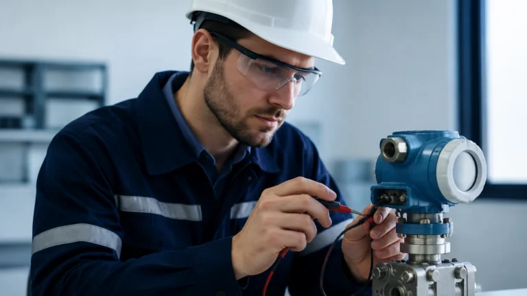
3. Zero Calibration: Once installed and under full process pressure (but zero flow), a "zero trim" must be performed to account for any stresses the piping might be exerting on the sensor.
4. Avoid Cavitation: Ensure the backpressure is sufficient to prevent the fluid from flashing or cavitating within the meter tubes.
Limitations and Application Boundaries
Despite their versatility, Coriolis meters are not a "silver bullet" for every application.
* Cost: They are significantly more expensive than electromagnetic or ultrasonic flowmeters.
* Size Constraints: As pipe diameters increase (above 250mm or 10 inches), the meters become extremely large, heavy, and prohibitively expensive.
* Pressure Drop: The diverted flow path in bent-tube designs can cause a significant pressure drop in high-viscosity fluids.
* Two-Phase Flow: While they handle some gas entrainment, high percentages of gas in liquid (or liquid in gas) can cause the tubes to stop vibrating (stalling), leading to measurement errors.
Integration with Level Measurement Systems
In many industrial setups, such as chemical batching or fuel storage, Coriolis meters work in tandem with level measurement instruments. While the Coriolis meter manages the transfer of mass, level sensors like those found on our Main Page monitor the inventory within the tanks.
For example, in a blending tank, a Welk radar level meter provides the primary safety and inventory data, while a Coriolis meter ensures the exact mass of each chemical component is added to the mixture. This combination ensures both process efficiency and high-quality output.
Frequently Asked Questions (FAQs)
Q: Does the viscosity of the fluid affect the Coriolis meter?
A: Generally, no. The Coriolis force is dependent on mass and velocity, not the internal friction (viscosity) of the fluid. However, high-viscosity fluids may cause a higher pressure drop across the meter.
Q: Can a Coriolis meter measure gas flow?
A: Yes, they are highly effective for high-pressure gas measurement. However, because gas has much lower density than liquid, the vibration signal is weaker, and the accuracy is typically lower (around ±0.5%).
Q: How often does a Coriolis meter need recalibration?
A: Because there are no moving parts to wear, the calibration is exceptionally stable. Many industrial users only recalibrate every 2 to 5 years, depending on internal quality standards and the corrosivity of the fluid.
Q: What is the difference between a straight-tube and a U-tube design?
A: U-tubes are generally more sensitive and offer a wider turndown ratio but are harder to clean and cause more pressure drop. Straight tubes are easier to drain and clean (CIP/SIP) and are ideal for shear-sensitive fluids or slurries.
Conclusion
Understanding how does a coriolis meter work is essential for any engineer looking to optimize process accuracy and reliability. By leveraging the phase shift of vibrating tubes to measure mass and the resonant frequency to measure density, these devices provide a comprehensive view of fluid dynamics that few other technologies can match. When paired with reliable level measurement instruments from Welk, they form the backbone of modern industrial automation and quality control.