4 Electrode Conductivity
4 Electrode Conductivity
In industrial liquid analysis, measuring the ability of a solution to conduct an electrical current—known as electrolytic conductivity—is essential for monitoring water quality, chemical concentrations, and process efficiency. While traditional two-electrode sensors are sufficient for clean, low-conductivity applications like ultrapure water, they often fail in demanding industrial environments due to polarization and fouling. This is where 4 electrode conductivity technology becomes the preferred choice for engineers requiring accuracy across a wide dynamic range.
Measurement Principles of 4 Electrode Conductivity
To understand the advantages of the four-electrode method, one must first understand the limitations of the classic two-electrode (amperometric) approach. In a two-electrode system, the same pair of electrodes is used to apply a voltage and measure the resulting current. At high conductivities or in the presence of electrode coating, a phenomenon called "polarization" occurs. A layer of ions builds up at the electrode surface, creating an additional resistance that the transmitter cannot distinguish from the liquid’s actual resistance, leading to significant measurement errors.
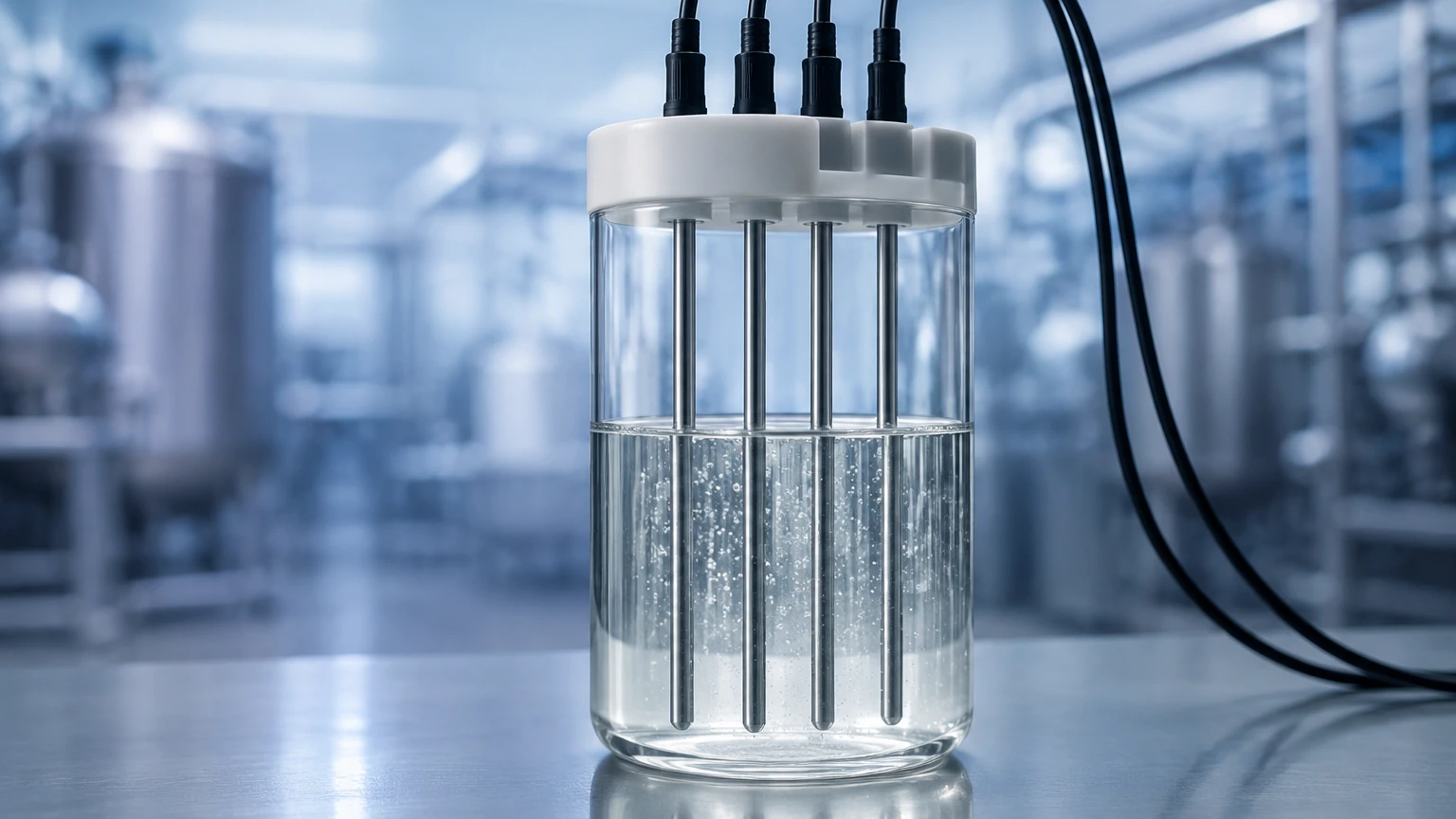
4 electrode conductivity sensors solve this by separating the current-driving electrodes from the voltage-sensing electrodes. The measurement principle follows these steps:
1. Current Excitation: An alternating current (AC) is applied to the two outer electrodes (the drive electrodes). This creates an electric field within the liquid.
2. Voltage Sensing: Two inner electrodes (the sense electrodes) measure the voltage drop across a specific segment of the liquid.
3. High Impedance Measurement: The voltage is measured using a high-impedance circuit, meaning almost no current flows through the sensing electrodes. Because there is no current flow at the sensing electrodes, polarization cannot occur at these points.
4. Ohm’s Law Calculation: The transmitter uses the known current (I) and the measured voltage (V) to calculate the conductance (G = I/V). When combined with the cell constant (K), the specific conductivity of the medium is determined.
This four-wire configuration also compensates for cable resistance and connector corrosion, as the voltage drop across the lead wires does not affect the high-impedance voltage measurement at the sensor head.
Comparing Conductivity Technologies
Choosing the right sensor requires an understanding of where 4-electrode technology sits relative to 2-electrode and inductive (toroidal) methods. The following table provides a comparison for process engineering selection.
| Feature | 2-Electrode Sensor | 4-Electrode Sensor | Inductive (Toroidal) |
| :— | :— | :— | :— |
| Measurement Range | Very Low (0.05 µS/cm to 2 mS/cm) | Wide (10 µS/cm to 1,000 mS/cm) | High (100 µS/cm to 2,000 mS/cm) |
| Sensitivity to Fouling | Very High | Moderate | Very Low |
| Polarization Error | High at high conductivity | Negligible | None |
| Ideal Application | Ultrapure water, condensate | Wastewater, chemical processing | Slurries, highly corrosive acids |
| Accuracy | Highest in low ranges | High across wide ranges | Moderate |
| Installation Size | Small | Small to Medium | Large (requires larger pipe) |
Key Evaluation Criteria for Industrial Applications
When specifying a 4 electrode conductivity system for a facility, engineers must evaluate several technical parameters to ensure long-term reliability and data integrity.
1. Cell Constant (K)
While 4-electrode sensors are designed to cover a broad range, the geometry of the electrodes still dictates the "cell constant." A lower cell constant is generally used for lower conductivity, while a higher constant is used for concentrated solutions. However, a major benefit of the 4-electrode design is that a single sensor can often replace multiple 2-electrode sensors that would otherwise be needed to cover the same range.
2. Material Compatibility
The electrodes must be chemically resistant to the process media. Common materials include:
* 316L Stainless Steel: Standard for water treatment and non-corrosive chemicals.
* Graphite: Excellent for general industrial use and resistant to many acids.
* Titanium or Hastelloy: Required for highly aggressive chemical environments.
* PEEK or PVDF Bodies: The insulation material must also withstand the process temperature and chemical makeup.
3. Temperature Compensation
Conductivity is highly temperature-dependent; typically, conductivity increases by about 2% per degree Celsius. Accurate 4 electrode conductivity measurements require an integrated temperature sensor (such as a Pt100 or Pt1000) located close to the electrodes to provide real-time linear or non-linear temperature compensation.
Practical Selection Table
| Industry | Application | Recommended Material | Conductivity Range |
| :— | :— | :— | :— |
| Water Treatment | Reverse Osmosis monitoring | 316L Stainless / PEEK | 10 – 2,000 µS/cm |
| Food & Beverage | CIP (Clean-in-Place) concentration | Graphite / Polypropylene | 1 – 500 mS/cm |
| Chemical | Acid/Base Dilution | Hastelloy / PTFE | 10 – 1,000 mS/cm |
| Wastewater | Effluent monitoring | Graphite / PVC | 100 – 10,000 µS/cm |
| Power Plant | Cooling tower blowdown | 316L Stainless | 500 – 5,000 µS/cm |
Installation Considerations
To achieve the rated accuracy of a 4-electrode sensor, physical installation must follow strict engineering guidelines. Improper placement is the leading cause of "drift" or unstable readings.
* Avoid Air Pockets: Sensors should be installed in a vertical pipe with upward flow or on the side of a horizontal pipe. Never install a sensor at the top of a pipe where air bubbles can collect, as air is non-conductive and will cause artificially low readings.
* Full Immersion: The entire electrode assembly must be fully submerged. Partial immersion changes the effective cell constant and invalidates the factory calibration.
* Wall Effects: 4-electrode sensors generate an electric field that extends beyond the physical electrodes. If the sensor is placed too close to a metallic pipe wall, the wall can interfere with the field. Always maintain the manufacturer-specified minimum clearance (typically 10mm to 20mm from the pipe wall).
* Flow Direction: While most 4-electrode sensors are not flow-sensitive, installing them so the flow flushes the electrode gap helps prevent the accumulation of solids or biological growth.
Maintenance and Calibration
Although 4 electrode conductivity sensors are more robust than 2-electrode versions, they are not maintenance-free.
Cleaning: If the electrodes become coated with oil, scale, or biological film, the voltage sensing will eventually be affected. Cleaning should be done with a soft brush and a suitable solvent (such as a mild detergent or a 5% HCl solution for calcium scale). Avoid abrasive materials that could scratch the electrode surface, especially if using graphite electrodes.
Calibration: Calibration should be performed using certified standard solutions that fall within the expected process range. It is important to note that conductivity standards are sensitive to CO2 absorption from the air, which can lower their value over time. Always use fresh standards and ensure the temperature is stable during the calibration process.
For comprehensive technical specifications on sensor integration and to explore various industrial instrument options, professionals can visit the Main Page of Welk for detailed product documentation.
Common Risks and Limitations
Despite their versatility, 4-electrode sensors have specific limitations:
1. Ultrapure Water Limits: In extremely low conductivity ranges (< 10 µS/cm), the 4-electrode method is less accurate than the 2-electrode method because the signal-to-noise ratio becomes unfavorable.
2. Heavy Slurries: While better than 2-electrode sensors, 4-electrode sensors can still be plugged by heavy slurries or fibrous materials. In these cases, an inductive (non-contact) sensor is usually a better choice.
3. Electromagnetic Interference (EMI): Because the sensing circuit is high-impedance, it can be sensitive to EMI from nearby high-power motors or variable frequency drives (VFDs). Shielded cabling and proper grounding are mandatory.
Frequently Asked Questions (FAQs)
Q: Can a 4-electrode sensor be used for seawater?
A: Yes. Seawater typically has a conductivity of around 50 mS/cm. A 4-electrode sensor is ideal for this range as it resists the polarization that would plague a 2-electrode sensor in such a high-salinity environment.
Q: How do I know if my sensor is fouled?
A: Most modern transmitters for 4-electrode sensors include diagnostic functions. If the drive voltage required to maintain the constant current exceeds a certain threshold, the transmitter will trigger a "fouling" or "electrode error" alarm.
Q: Is the cable length limited for 4-electrode sensors?
A: While the 4-wire technique compensates for cable resistance, the capacitance of very long cables (over 50 meters) can introduce phase shifts in the AC signal. It is best to use a transmitter with a pre-amplifier or keep the cable runs within the manufacturer's recommended limits.
Conclusion
The implementation of 4 electrode conductivity measurement provides industrial operators with a high degree of reliability across diverse process conditions. By eliminating the errors associated with polarization and providing a wide dynamic range, these sensors reduce the need for frequent recalibration and multiple sensor types. When selecting a system, engineers should prioritize material compatibility and ensure installation environments are free of air pockets to maximize the lifespan and accuracy of the instrument. For further assistance in selecting the correct level and analytical instrumentation, reviewing the available resources on the Main Page can provide necessary guidance for complex automation projects.