Pune Techtrol Radar Level Transmitter
Pune Techtrol Radar Level Transmitter: An Engineering Guide to Selection and Application
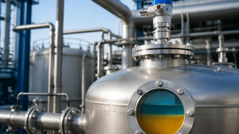
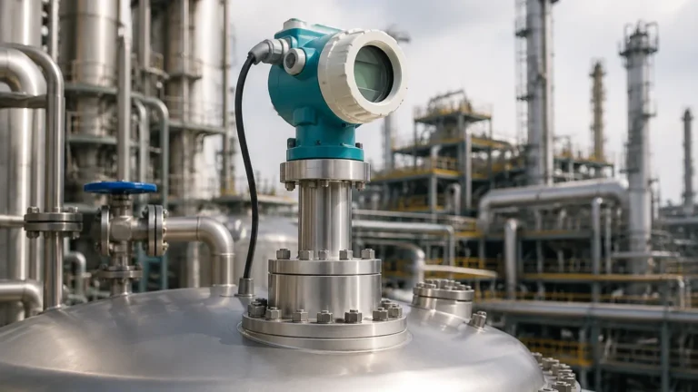
In the landscape of industrial automation, precise level measurement is a cornerstone of process safety, inventory management, and operational efficiency. Among the various technologies available, radar-based systems have emerged as a preferred solution for challenging environments. This guide examines the pune techtrol radar level transmitter, exploring its underlying physics, selection criteria, and the practical considerations necessary for successful integration into industrial workflows.
1. Principles of Radar Level Measurement
Before selecting a specific instrument, it is essential to understand the physics of radar technology. Radar (Radio Detection and Ranging) level measurement relies on the propagation of electromagnetic waves. Unlike ultrasonic sensors, which use sound waves and are susceptible to air temperature and pressure changes, radar waves travel at the speed of light and are largely unaffected by the vapor space composition.
Time of Flight (ToF)
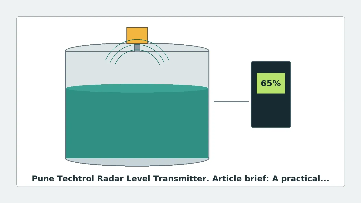
Most radar transmitters operate on the Time of Flight principle. The device emits a high-frequency microwave signal toward the product surface. The signal reflects off the surface and returns to the antenna. The transmitter measures the time interval between emission and reception to calculate the distance ($D$) using the formula:
$$D = \frac{c \times t}{2}$$
Where $c$ is the speed of light and $t$ is the measured time. The actual level is then derived by subtracting this distance from the total tank height (reference point).
FMCW vs. Pulse Radar
Modern Radar Level Meters generally utilize one of two modulation techniques:
1. Pulse Radar: The transmitter emits a series of short microwave pulses. This method is energy-efficient and suitable for simple liquid applications.
2. Frequency Modulated Continuous Wave (FMCW): The transmitter emits a continuous signal with a constantly changing frequency. The difference between the frequency of the emitted signal and the reflected signal is proportional to the distance. FMCW offers higher accuracy and better signal-to-noise ratios, making it ideal for solids and turbulent liquids.
The Role of Dielectric Constant ($ε_r$)
The reliability of a radar reflection depends on the dielectric constant of the medium. Materials with high dielectric constants (e.g., water, $ε_r \approx 80$) reflect signals strongly. Materials with low dielectric constants (e.g., hydrocarbons, $ε_r < 2$) absorb or transmit more energy, resulting in weaker return signals. The pune techtrol radar level transmitter is designed with high sensitivity to detect these faint echoes in low-dielectric applications.
2. Types of Pune Techtrol Radar Level Transmitters
Pune Techtrol provides two primary configurations of radar transmitters to suit different process geometries and material characteristics: Non-Contact Radar and Guided Wave Radar (GWR).
Non-Contact Radar
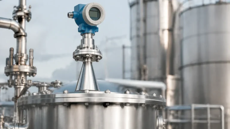
These transmitters are mounted at the top of the vessel and do not touch the process media. They are ideal for corrosive, viscous, or hygienic applications where contact would lead to probe degradation or contamination. They typically operate at frequencies such as 26 GHz or 80 GHz. Higher frequencies allow for smaller antenna sizes and narrower beam angles, which help avoid internal tank obstructions.
Guided Wave Radar (GWR)
In GWR systems, the microwave pulse is guided along a physical probe (cable or rod). This concentrates the energy and minimizes signal loss. GWR is particularly effective for low-dielectric liquids, foaming surfaces, and interface measurement (e.g., oil over water). Because the signal is contained near the probe, it is less affected by tank internal structures or turbulence.
3. Technical Selection Criteria
Selecting the correct pune techtrol radar level transmitter requires a detailed analysis of the process environment. The following table provides a generalized selection framework based on typical industrial requirements.
Selection Table
| Process Variable | Non-Contact Radar (High Freq) | Guided Wave Radar (GWR) | Recommended Action |
| :— | :— | :— | :— |
| Liquid Level | Excellent for clean liquids | Excellent for all liquids | Choose Non-Contact for corrosive media. |
| Solid/Powder Level | Preferred (80 GHz) | Limited to short ranges | Use Non-Contact to avoid probe pull-down. |
| Turbulent Surface | Good (with software filtering) | Excellent | GWR is more stable in agitation. |
| Heavy Foam | Moderate (signal may scatter) | Good (penetrates foam) | Test GWR if foam is dense and thick. |
| High Temperature | Up to 250°C (482°F) | Up to 400°C (752°F) | Check specific model temperature ratings. |
| Dielectric Constant | Requires $ε_r > 1.4$ | Can handle $ε_r \ge 1.2$ | Use GWR for very low DK hydrocarbons. |
| Internal Obstructions | Requires clear path | Probes can be positioned away | Use high-frequency radar for narrow paths. |
4. Installation Considerations and Best Practices
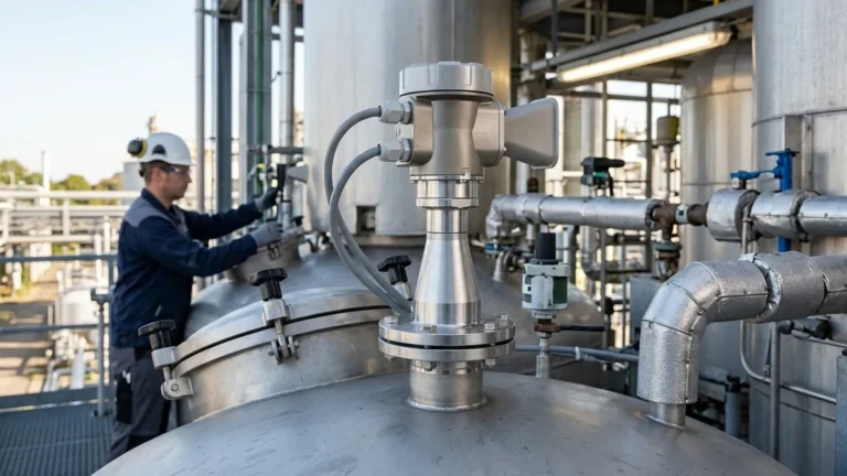
The performance of a pune techtrol radar level transmitter is heavily dependent on correct installation. Even the most advanced sensor will fail if the signal path is compromised.
Nozzle Geometry
The mounting nozzle should be as short and wide as possible. If the nozzle is too long or narrow, the radar signal may reflect off the nozzle walls (ringing), creating a "dead zone" or false echo at the top of the tank. Ideally, the antenna should extend slightly below the nozzle into the vessel.
Beam Angle and Obstructions
Every non-contact radar has a beam angle (typically 3° to 10°). The "footprint" of the radar signal expands with distance. Engineers must ensure that no internal structures—such as ladders, agitators, or heating coils—intersect the radar beam.
* Formula for Beam Diameter ($W$): $W = 2 \times L \times \tan(\theta/2)$, where $L$ is distance and $ɵ$ is the beam angle.
Mounting Position
* Avoid the Center: Do not mount the transmitter in the exact center of a domed tank, as this can cause multiple reflections to converge, amplifying noise.
* Avoid the Wall: Stay at least 200 mm (8 inches) away from the tank wall to prevent interference from wall weld seams or buildup.
* Inlet Stream: Never mount the transmitter directly over the product inlet. The falling stream will scatter the signal and cause erratic readings.
5. Limitations and Application Risks
While radar is highly versatile, it is not a "one-size-fits-all" solution. Understanding its limitations prevents costly commissioning failures.
1. Condensation and Buildup: While radar can penetrate some vapor, heavy condensation or crystalline buildup on the antenna lens can attenuate the signal. Pune Techtrol often offers air purging or PTFE-coated lenses to mitigate this.
2. Extremely Low Dielectrics: For materials like liquid nitrogen or certain dry powders ($ε_r < 1.4$), the reflection may be too weak for standard non-contact radar. In these cases, GWR or a specialized high-sensitivity Radar Level Meters configuration is required.
3. Vacuum and High Pressure: While radar works in a vacuum, the mechanical seal of the transmitter must be rated for the specific pressure. High-pressure steam can also slightly change the propagation speed of the signal, requiring a "vapor compensation" factor in high-accuracy custody transfer applications.
6. Maintenance and Troubleshooting
One of the primary advantages of the pune techtrol radar level transmitter is its lack of moving parts, which significantly reduces maintenance requirements. However, periodic checks are recommended:
* False Echo Mapping: Over time, new obstructions (like scale buildup on tank walls) may appear. Most Techtrol units allow for "False Echo Suppression," where the transmitter is taught to ignore static reflections from internal structures.
* Signal Strength Monitoring: A decreasing signal-to-noise ratio often indicates buildup on the antenna or a degrading seal. Monitoring this via HART or Modbus can enable predictive maintenance.
* Loop Calibration: Ensure the 4-20mA output correctly corresponds to the digital distance reading by performing a dry-run or using a reference tape measure.
7. Frequently Asked Questions (FAQs)
Q: Can the Pune Techtrol radar transmitter measure solids?
A: Yes, but it requires a high-frequency (typically 26GHz or 80GHz) non-contact model. Solids have an angle of repose that can deflect the radar signal away from the antenna, so proper aiming and high-sensitivity electronics are necessary.
Q: How does foam affect the measurement?
A: Light, airy foam is often transparent to radar. However, dense, wet foam (like that found in some chemical reactors) can reflect the signal prematurely or absorb it entirely. In cases of thick foam, Guided Wave Radar is generally more reliable as the probe stays in contact with the liquid.
Q: Is the transmitter suitable for hazardous areas?
A: Pune Techtrol offers versions with ATEX, IECEx, or PESO certifications. Always verify the specific Ex-rating (Intrinsic Safety or Flameproof) matches your plant's zone classification before installation.
Q: What is the minimum distance the radar can measure?
A: This is known as the "Blocking Distance" or "Dead Zone." It typically ranges from 50 mm to 300 mm (2 to 12 inches) depending on the antenna type and frequency. Ensure the maximum expected level does not enter this zone.
8. Summary for International Procurement
When sourcing a pune techtrol radar level transmitter for international projects, buyers should confirm the following technical specifications to ensure compatibility:
* Process Connection: Confirm if ANSI, DIN, or JIS flanges are required.
* Output Protocol: Standard 4-20mA is common, but HART, Profibus, or Foundation Fieldbus may be needed for integration with modern Distributed Control Systems (DCS).
* Material Compatibility: Ensure the wetted parts (SS316L, Hastelloy, PTFE) are compatible with the process chemical.
* Documentation: Request material test reports (MTRs), calibration certificates, and hazardous area certifications as part of the procurement package.
By adhering to these engineering principles and installation guidelines, the pune techtrol radar level transmitter serves as a robust and accurate instrument for demanding industrial level measurement tasks. Whether managing water treatment facilities or complex chemical reactors, understanding the interaction between the microwave signal and the process media is the key to long-term reliability.