Radar Level Transmitter Temperature Compensation
Radar Level Transmitter Temperature Compensation: An Engineering Guide
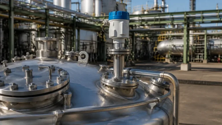
In the landscape of industrial automation, precise level measurement is a cornerstone of process safety and efficiency. Among the various technologies available, Radar Level Meters have emerged as the preferred choice for challenging environments. However, a common point of discussion among instrumentation engineers is the role of temperature. While radar technology is inherently more robust against atmospheric changes than ultrasonic methods, the implementation of radar level transmitter temperature compensation remains a critical factor for achieving high-accuracy measurements in fluctuating thermal conditions.
This guide explores the principles of radar measurement, the technical necessity of temperature compensation, and practical considerations for selecting and installing equipment in high-temperature industrial applications.
Principles of Radar Level Measurement
To understand why temperature compensation is necessary, one must first understand how radar level transmitters operate. Most modern industrial radar units utilize either Pulse Radar or Frequency Modulated Continuous Wave (FMCW) technology.
Time of Flight (ToF)
At its core, a radar sensor emits electromagnetic pulses or continuous wave signals toward the surface of the medium. These waves travel at the speed of light ($c \approx 300,000$ km/s). When the signal hits the product surface, it is reflected back to the antenna. The transmitter measures the time elapsed between emission and reception to calculate the distance ($d$) using the formula:
$$d = \frac{c \times t}{2}$$
Where:
* $c$ is the speed of light.
* $t$ is the transit time.
Radar vs. Ultrasonic: The Temperature Factor
Unlike ultrasonic waves, which are mechanical sound waves that rely on the air medium for propagation, radar waves are electromagnetic. The speed of sound is highly dependent on air temperature, density, and humidity. Consequently, ultrasonic sensors require aggressive temperature compensation to account for the changing speed of sound in the vapor space.
Radar waves, however, maintain a nearly constant speed regardless of air temperature or pressure. This leads to a common misconception that radar transmitters do not require temperature compensation. In reality, while the *wave speed* is stable, the *hardware* and the *process environment* are not.
The Necessity of Radar Level Transmitter Temperature Compensation
Even though the electromagnetic signal is stable, temperature fluctuations affect the measurement accuracy through three primary channels: electronic drift, physical expansion of the antenna, and changes in the dielectric properties of the medium.
1. Electronic Component Stability
The internal circuitry of a radar transmitter, including the high-frequency oscillator and the microprocessor, is sensitive to thermal changes. As the temperature inside the transmitter housing rises, the frequency of the internal clock or the stability of the microwave generator can drift. Without radar level transmitter temperature compensation, this drift can introduce small but cumulative timing errors, which translate into distance measurement inaccuracies.
2. Antenna Thermal Expansion
In high-precision applications, the physical dimensions of the antenna (horn, rod, or lens) matter. As materials heat up, they expand. For a 26GHz or 80GHz radar, where wavelengths are measured in millimeters, a physical expansion of the waveguide or antenna mounting can shift the reference point of the measurement. Compensation algorithms account for these mechanical changes based on the temperature reported by internal sensors.
3. Vapor Space Dielectric Changes
While the speed of light is constant in a vacuum, it slows down slightly when passing through dense gases or high-pressure vapors. In high-temperature steam applications (such as boiler drum level), the dielectric constant of the vapor space increases. This can cause the radar signal to slow down, leading to a "measured distance" that is longer than the actual distance. Advanced transmitters use temperature and pressure data to compensate for this propagation delay.
Selection Criteria for Different Temperature Ranges
When specifying Radar Level Meters, engineers must match the transmitter hardware to the process temperature. Standard units are typically rated for ambient conditions, while specialized versions are required for cryogenic or high-heat processes.
Practical Selection Table
| Feature | Standard Radar | Mid-Range Industrial | High-Temperature / High-Pressure |
| :— | :— | :— | :— |
| Process Temp Range | -40°C to +80°C | -40°C to +150°C | -196°C to +450°C |
| Antenna Material | PP / PTFE | PTFE / 316L SS | Ceramic Seal / 316L or Hastelloy |
| Cooling Method | Natural Convection | Integrated Heat Sink | Cooling Fins / Air Purge |
| Compensation | Internal PCB Sensor | PCB + Antenna Sensor | Multi-point Thermal Modeling |
| Typical Application | Water storage, plastic pellets | Chemical reactors, oil tanks | Bitumen, molten salt, steam boilers |
Hardware Design for Thermal Management
To ensure the effectiveness of radar level transmitter temperature compensation, the physical design of the instrument must support thermal isolation. Manufacturers like Welk utilize several engineering strategies to protect the sensitive electronics from process heat.
Thermal Dissipators (Cooling Fins)
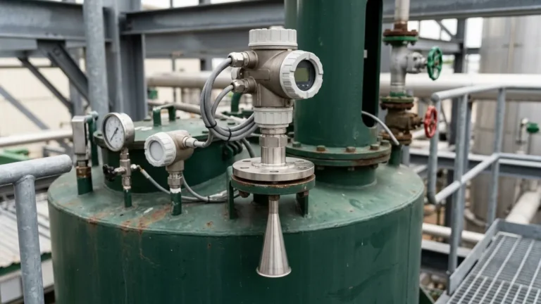
For processes exceeding 150°C, cooling fins are often integrated between the process flange and the transmitter head. These fins increase the surface area for heat dissipation, ensuring that the temperature at the electronics housing remains within the operating limit (usually < 85°C) even if the process is significantly hotter.
Ceramic and Glass Seals
In extreme heat, standard PTFE seals may soften or fail. High-temperature radar units employ ceramic or specialized glass seals. These materials provide a gas-tight barrier that prevents hot process vapors from entering the waveguide while maintaining a stable dielectric window for the radar signal.
Standoff Pipes
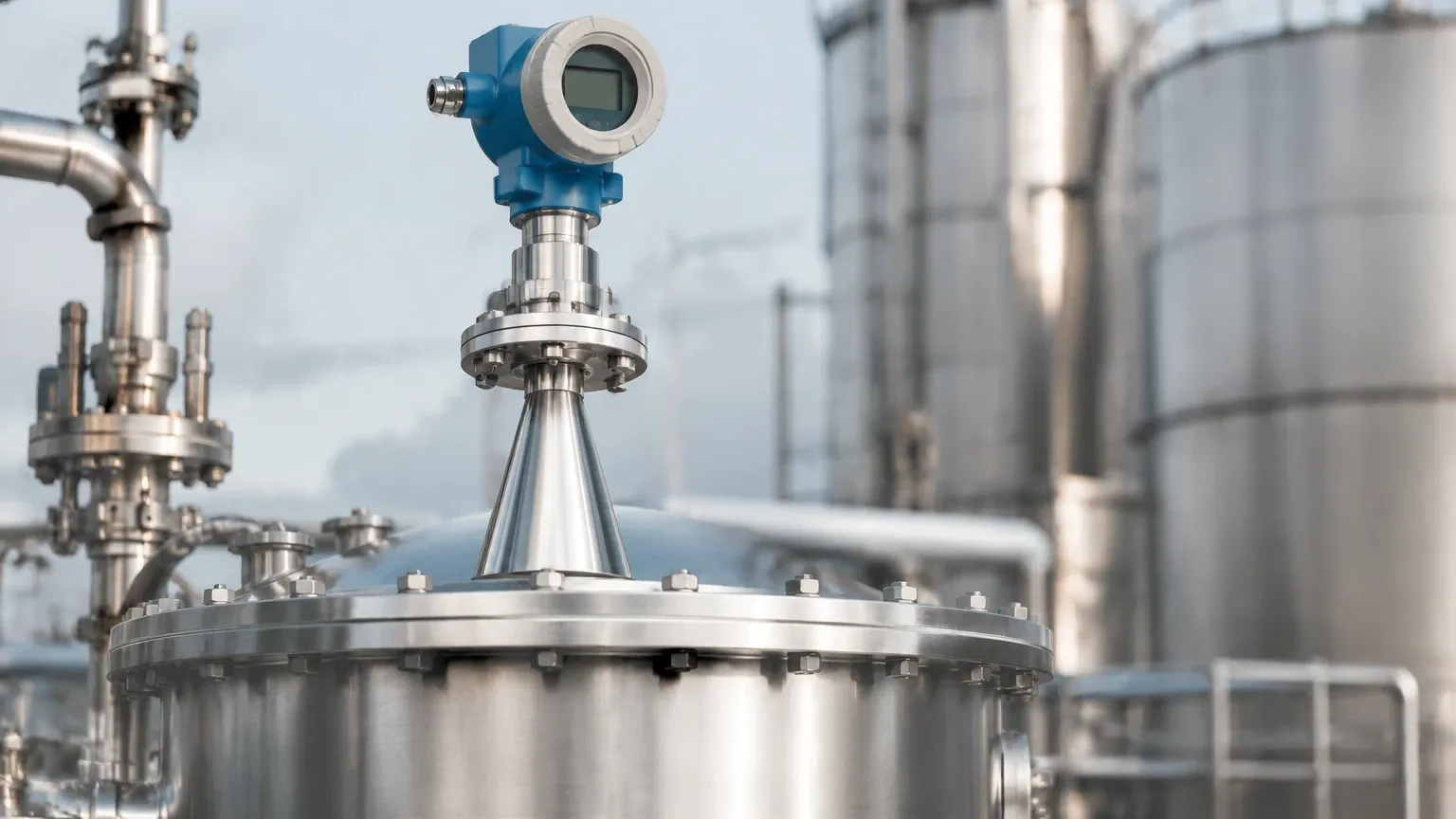
Increasing the distance between the transmitter and the process is a simple yet effective way to manage temperature. A standoff pipe (nozzle) allows the heat to dissipate before reaching the sensor. However, the internal diameter of the standoff must be chosen carefully to avoid signal interference from the pipe walls, especially with lower-frequency radars.
Installation Considerations and Best Practices
Proper installation is as important as the compensation technology itself. To maximize the accuracy of your Radar Level Meters, consider the following:
1. Avoid Direct Sunlight: In outdoor installations, solar radiation can heat the transmitter housing well above the ambient air temperature. Using a sunshade prevents localized overheating and reduces the workload on the internal temperature compensation circuits.
2. Insulation Boundaries: When insulating a tank, do not insulate the transmitter's cooling fins or the electronics housing. The housing needs to dissipate heat generated by its own internal circuits.
3. Nozzle Length: Ensure the antenna extends slightly beyond the nozzle (unless using a nozzle-specific lens antenna). This prevents internal reflections that can be exacerbated by thermal expansion of the nozzle itself.
4. Orientation: Install the unit vertically. Any tilt can cause the signal to reflect away from the receiver, a problem that becomes more pronounced if the mounting flange warps slightly due to extreme heat.
Limitations of Temperature Compensation
While radar level transmitter temperature compensation is highly effective, it has physical limits.
* Thermal Shock: Rapid temperature changes (e.g., during a CIP process in the food industry) can cause temporary instability. The sensor needs time for the internal components to reach thermal equilibrium before the highest accuracy is restored.
* Extreme Pressures: In high-pressure steam, the change in the refractive index of the gas is so significant that temperature compensation alone may not suffice. In these cases, a reference target (a fixed mechanical pin at a known distance) is sometimes used to calibrate the signal speed in real-time.
* Electronics Limits: No amount of software compensation can save a transmitter if the ambient temperature at the housing exceeds the rated limit (typically 80°C to 85°C). In such cases, external cooling or remote-mounted electronics are mandatory.
Frequently Asked Questions (FAQ)
Q: Does the temperature of the liquid being measured affect the radar accuracy?
A: Indirectly, yes. The temperature of the liquid affects its dielectric constant (εr). A lower εr results in a weaker reflected signal. While this doesn't change the "distance" measured, it can affect the signal-to-noise ratio. The transmitter's compensation primarily focuses on the instrument's internal timing and the signal's travel path.
Q: How do I know if my application requires a high-temperature radar?
A: If your process temperature consistently exceeds 130°C, or if there are frequent temperature spikes, you should opt for a model with a dedicated heat dissipator and specialized sealing. Always check the technical datasheet for the "Process Temperature" vs. "Ambient Temperature" ratings.
Q: Is 80GHz radar better for high-temperature applications than 26GHz?
A: 80GHz radars have smaller antennas and narrower beams, making them easier to install on smaller nozzles or through isolation valves. However, 26GHz radars are often more robust in heavy steam or dust. Both frequencies can be equipped with effective radar level transmitter temperature compensation, so the choice usually depends on the tank geometry and the presence of obstacles.
Conclusion
For international buyers and plant engineers, selecting the right level measurement solution requires a balance of technology and application knowledge. While Radar Level Meters offer unparalleled reliability, ensuring they are equipped with robust temperature compensation and appropriate thermal hardware is essential for long-term success. By understanding the physics of thermal drift and following rigorous installation standards, industrial facilities can achieve precise level control even in the most demanding thermal environments.
Download Radar Level Transmitter Temperature Compensation as a PDF