Solvent Capture Systems
Solvent Capture Systems
Solvent capture systems are essential infrastructure in modern industrial chemistry, pharmaceuticals, and manufacturing. These systems are designed to recover volatile organic compounds (VOCs) and other solvents from process exhaust or liquid waste streams, preventing atmospheric pollution and allowing for the reuse of expensive chemical resources. In the context of industrial automation, the efficiency of a solvent capture system relies heavily on precise instrumentation, particularly level measurement, to manage the accumulation, separation, and storage of recovered media.
For engineers and plant managers, selecting the correct instrumentation for these systems requires a deep understanding of both the chemical properties of the solvents and the physics of the measurement technologies employed. This guide explores the engineering principles of level measurement within solvent capture systems and provides a framework for selecting the most reliable solutions.
The Role of Level Measurement in Solvent Capture Systems
In a typical solvent capture cycle—whether utilizing carbon adsorption, condensation, or membrane separation—the recovered solvent is eventually collected in a liquid state. Accurate level monitoring is critical at several stages:
1. Collection Tanks: Monitoring the volume of raw solvent-laden liquids before processing.
2. Phase Separators: In systems where solvents are recovered alongside water (e.g., steam stripping), level sensors must identify the interface between the solvent and the aqueous layer.
3. Distillation Columns: Maintaining the precise liquid level in the reboiler or reflux drum to ensure thermal efficiency.
4. Storage and Day Tanks: Ensuring inventory accuracy and preventing overfill conditions that could lead to hazardous spills.
Failure to maintain accurate level data can result in pump cavitation, process downtime, or environmental non-compliance. To explore the full range of instrumentation available for these tasks, professionals can refer to the Main Page of our technical catalog for specific product data.
Measurement Principles for Solvent Recovery
Before selecting a device for solvent capture systems, it is necessary to understand how different measurement principles interact with solvent properties such as dielectric constant, vapor pressure, and density.
Radar Level Measurement (ToF)
Radar level meters operate on the Time-of-Flight (ToF) principle. They emit high-frequency microwave pulses (typically in the 26 GHz or 80 GHz range) that travel at the speed of light. When these pulses hit the surface of the solvent, they are reflected back to the sensor. The distance is calculated based on the time interval between emission and reception.
* Advantages: Radar is non-contact and largely unaffected by changes in pressure, temperature, or the presence of heavy vapors. This makes it the gold standard for volatile solvents like toluene, benzene, or alcohols.
* Consideration: The strength of the reflection depends on the dielectric constant (εr) of the solvent. Low-dielectric solvents (e.g., hexane, εr ≈ 1.9) reflect less energy than water (εr ≈ 80), requiring high-sensitivity radar units.
Ultrasonic Level Sensing
Ultrasonic sensors emit acoustic pressure waves that reflect off the liquid surface. The device measures the time taken for the sound echo to return.
* Advantages: Cost-effective for simple, atmospheric storage tanks containing non-volatile aqueous solutions.
* Limitations: In solvent capture systems, the gas space often contains high concentrations of solvent vapors. Since the speed of sound changes depending on the gas composition and temperature, ultrasonic sensors can experience significant errors or signal loss in these environments.
Hydrostatic Pressure Measurement
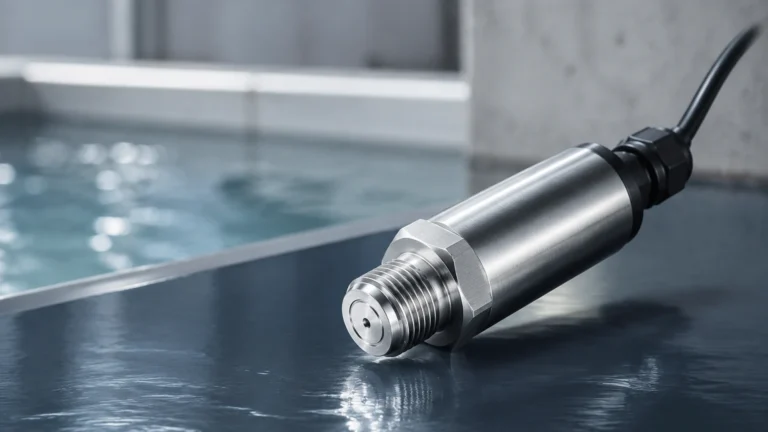
This principle measures the pressure exerted by the liquid column at the bottom of the tank. The level is calculated using the formula: *Level = Pressure / (Density × Gravity)*.
* Advantages: Simple to install and highly reliable for vented tanks.
* Limitations: Solvents often have varying densities depending on temperature or purity. If the density of the recovered solvent fluctuates, the level reading will drift unless the system includes active density compensation.
Magnetic Level Gauges
Magnetic gauges use a float containing a magnet that moves with the liquid level inside a bypass chamber. This magnet actuates external visual flags or a continuous transmitter.
* Advantages: Provides a clear visual indication without requiring power. It is ideal for high-pressure solvent recovery vessels where a physical barrier between the process and the electronics is preferred.
Selection Guide for Solvent Capture Instrumentation
Choosing the right technology depends on the specific requirements of the solvent capture system. The following table provides a general comparison for engineering selection.
| Technology | Typical Accuracy | Media Compatibility | Best Use Case |
| :— | :— | :— | :— |
| 80 GHz Radar | ±1 mm | All solvents, including low εr | High-precision recovery tanks |
| Guided Wave Radar | ±2 mm | Low εr, foam-prone liquids | Interface measurement (Solvent/Water) |
| Ultrasonic | ±0.25% of range | Aqueous or non-volatile solvents | Open sumps and water treatment |
| Hydrostatic | ±0.1% to 0.5% | Consistent density fluids | Large outdoor storage tanks |
| Magnetic Gauge | ±5 mm | Hazardous/High-pressure solvents | Visual monitoring & bypass applications |
Installation and Engineering Considerations
When integrating level sensors into solvent capture systems, several mechanical and electrical factors must be addressed to ensure long-term performance.
1. Chemical Compatibility
Solvents are often aggressive toward standard elastomers and plastics. Wetted parts should be specified in high-grade stainless steel (316L), Hastelloy, or PTFE. For example, Viton O-rings may swell and fail when exposed to certain ketones or esters; in such cases, Kalrez or FFKM seals are required.
2. Vapor and Condensation Management
Solvent recovery processes often involve high humidity or saturated vapors. In radar applications, condensation on the antenna can attenuate the signal. Selecting a radar with a lens antenna or a flush-mounted PTFE face helps shed droplets and prevents buildup. For ultrasonic sensors, vapor compensation is rarely sufficient for high-concentration solvent environments, making radar the preferred choice.
3. Hazardous Area Certifications
Most solvents are flammable, classifying the capture area as a hazardous zone. Instruments must carry appropriate certifications such as ATEX, IECEx, or UL/CSA (Class I, Div 1). Both the sensor head and the wiring method (e.g., intrinsically safe or explosion-proof) must comply with local safety regulations.
4. Tank Geometry and Obstructions
Internal structures like agitators, heating coils, or baffles can create false echoes for radar and ultrasonic sensors. Modern instruments utilize "false signal suppression" software to map out these obstructions. However, for the best results, sensors should be mounted at least 200 mm (approx. 8 inches) away from the tank wall and clear of the filling stream.
Challenges and Limitations in Solvent Capture
While modern instrumentation is highly advanced, certain conditions in solvent capture systems remain challenging:
* Foaming: During the distillation or stripping phase, solvents may foam. Foam can absorb ultrasonic and radar signals. Guided wave radar (GWR) is often the best solution here, as the probe helps guide the signal through the foam to the true liquid surface.
* Vacuum Conditions: Some solvent recovery occurs under vacuum to lower the boiling point. Pressure-based sensors must be absolute pressure types or use differential pressure (DP) cells to account for the vacuum in the headspace.
* Turbulence: Rapid filling or agitation can cause surface ripples. Software damping and the use of stilling wells (pipes installed inside the tank to provide a calm surface) are recommended for these scenarios.
Implementation Checklist for Project Engineers
Before finalizing the design of a solvent capture system, confirm the following data points:
* [ ] Dielectric Constant: Is the solvent's εr above 1.4? (Determines radar sensitivity).
* [ ] Operating Temperature/Pressure: Will the sensor withstand the maximum process limits?
* [ ] Vapor Profile: Is the headspace prone to heavy condensation or gas stratification?
* [ ] Interface Requirements: Do you need to measure the total level or the boundary between two liquids?
* [ ] Output Protocol: Does the facility require 4-20mA HART, Modbus, or Profibus integration?
Frequently Asked Questions (FAQs)
Q: Can I use a standard ultrasonic sensor for acetone recovery?
A: It is not recommended. Acetone has a high vapor pressure, and the vapors significantly alter the speed of sound, leading to inaccurate readings. A non-contact radar sensor is a much more reliable choice for acetone.
Q: How do I measure the interface between a solvent and water?
A: Guided Wave Radar (GWR) is the most effective technology for this. It can detect the change in dielectric constant at the top layer (solvent) and the much higher dielectric constant of the water layer below, providing both levels simultaneously.
Q: Is 80 GHz radar better than 26 GHz for solvent tanks?
A: Generally, yes. 80 GHz radar has a narrower beam angle, which makes it easier to install in small tanks or vessels with internal obstructions. It also provides better resolution for low-dielectric solvents.
Conclusion
Effective solvent capture systems are a cornerstone of sustainable industrial operations. By selecting level measurement instruments based on the physical principles of radar, hydrostatic pressure, or magnetic buoyancy, engineers can ensure their systems operate at peak efficiency. Understanding the limitations of each technology—particularly regarding vapor interference and chemical compatibility—is the key to preventing costly maintenance and environmental risks. For more technical resources and product selection tools, visit the Main Page to consult with application specialists.