Radar Level Sensor Range
Radar Level Sensor Range: A Technical Guide for Industrial Applications
In industrial process control, selecting the appropriate instrumentation requires a deep understanding of how environmental and physical variables interact with sensor technology. Among the most critical specifications for any level measurement task is the radar level sensor range. This parameter defines the maximum and minimum distances over which a device can reliably track a material surface. However, "range" in a laboratory setting often differs from "effective range" in a pressurized chemical reactor or a dusty grain silo.
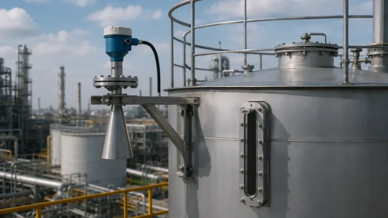
For engineers and procurement specialists, understanding the nuances of Radar Level Meters is essential for ensuring long-term operational reliability and safety. This guide explores the principles of radar measurement, the factors that dictate sensor range, and practical selection criteria for industrial environments.
Understanding Radar Measurement Principles
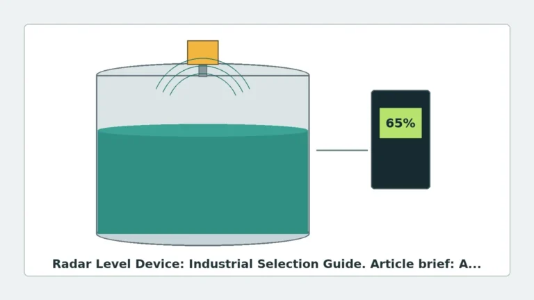
Radar level measurement is a non-contact technology that utilizes electromagnetic waves—specifically microwaves—to determine the distance to a product surface. The two primary methods used in industrial radar sensors are Pulse Radar and Frequency Modulated Continuous Wave (FMCW).
Pulse Radar (Time of Flight)
Pulse radar sensors emit a series of short microwave pulses toward the target material. The device measures the time it takes for the pulse to travel to the surface and reflect back to the receiver. Since the speed of light is constant, the distance is calculated using the formula:
*Distance = (Speed of Light × Time of Flight) / 2*.
Pulse radar is often favored for its lower power consumption and is suitable for many liquid level applications where the range is moderate (typically up to 30 meters).
FMCW (Frequency Modulated Continuous Wave)
FMCW radar does not send discrete pulses. Instead, it emits a continuous signal with a frequency that changes linearly over time (a frequency sweep). The reflected signal is received and compared to the signal being emitted at that exact moment. The difference in frequency (the "beat frequency") is directly proportional to the distance.
FMCW technology generally offers higher accuracy and a much greater radar level sensor range, often reaching up to 100 meters or more. It is particularly effective in complex environments where high signal resolution is required to distinguish the true level from false echoes caused by tank internals.
Key Factors Influencing Radar Level Sensor Range
The maximum distance a radar sensor can measure is not a fixed value; it is highly dependent on the signal-to-noise ratio. Several factors can attenuate the signal, effectively shortening the usable range.
1. Dielectric Constant (εr)
The dielectric constant of the medium being measured is perhaps the most significant factor in determining range. Materials with high dielectric constants, such as water (εr ≈ 80), reflect a large portion of the radar signal back to the sensor. Conversely, materials with low dielectric constants, such as hydrocarbons, oils, or plastic pellets (εr < 2.0), allow the microwave energy to penetrate the material, resulting in a much weaker reflection.
When measuring low-dielectric materials, the effective radar level sensor range is significantly reduced. In these cases, high-sensitivity FMCW sensors or specialized antenna designs are required to capture the faint return signal.
2. Surface Conditions
A calm, flat liquid surface acts like a mirror, reflecting the signal directly back to the antenna. However, turbulence, waves, or foaming can scatter the signal in different directions. Foam, in particular, can absorb microwave energy, leading to signal loss. In solid applications, the angle of repose and the particle size of the material also influence how the signal is reflected.
3. Antenna Gain and Beam Angle
The antenna focuses the microwave energy into a beam. A larger antenna or a higher-frequency sensor typically produces a narrower beam with higher "gain." A narrow beam concentrates the energy on the target, providing a stronger return signal and allowing for a longer measurement range. This is especially important in tall, narrow silos where a wide beam would reflect off the walls, creating interference.
The Role of Frequency in Range and Accuracy
Industrial radar level meters typically operate in three frequency bands: 6GHz, 26GHz, and 80GHz. Each has distinct advantages regarding range and application suitability.
| Frequency Band | Common Range | Typical Beam Angle | Primary Applications |
| :— | :— | :— | :— |
| 6GHz (C-Band) | Up to 30m | 20° – 30° | Applications with heavy steam, foam, or condensation. |
| 26GHz (K-Band) | Up to 70m | 8° – 12° | Standard liquid and solid storage; versatile for most industries. |
| 80GHz (W-Band) | Up to 120m | 3° – 4° | Tall silos, narrow nozzles, high-precision liquid measurement. |
80GHz Technology
The shift toward 80GHz technology has revolutionized the radar level sensor range. Because the wavelength is shorter, the antenna can be smaller while still achieving a very narrow beam angle (as low as 3 degrees). This allows the sensor to measure accurately over long distances even in vessels with internal obstructions like agitators or heating coils. Furthermore, 80GHz sensors have a much smaller "dead zone" (blocking distance) at the top of the tank, maximizing the usable volume of the vessel.
Selection Table: Matching Range to Application
When selecting a radar level meter, engineers must balance the required range with the process conditions. The following table provides a general guideline for technology selection.
| Material Type | Required Range | Recommended Technology | Considerations |
| :— | :— | :— | :— |
| Water/Aqueous Solutions | 0 – 30m | 26GHz Pulse/FMCW | High reflection; standard horn antenna is sufficient. |
| Heavy Oil/Bitumen | 0 – 20m | 6GHz or 26GHz | High temperatures; potential for buildup on antenna. |
| Plastic Pellets/Powder | 30m – 100m | 80GHz FMCW | Low dielectric; requires high gain and narrow beam. |
| Corrosive Chemicals | 0 – 15m | 26GHz (PTFE Flange) | Non-contact is essential; material compatibility is key. |
| Large Grain Silos | 50m – 120m | 80GHz FMCW | Dust and long distances require high-frequency precision. |
Installation Considerations and the "Dead Zone"
The physical installation of a radar level meter significantly impacts its effective performance. One of the most misunderstood aspects of radar level sensor range is the "Dead Zone" or "Blocking Distance."
The Dead Zone
Every radar sensor has a minimum distance it can measure, usually starting from the lower edge of the antenna. In this zone, the sensor cannot accurately distinguish between the emitted pulse and the reflected signal. For older 6GHz or 26GHz units, this dead zone might be 300mm to 500mm. Modern 80GHz sensors have reduced this to less than 100mm, allowing for measurement nearly to the top of the tank.
Nozzle Geometry
The nozzle on which the sensor is mounted must be designed to avoid signal interference. If the nozzle is too narrow or too long, the radar signal will reflect off the nozzle walls before it even enters the tank. This creates "ringing" or false echoes that can mask the true level, especially when the tank is nearly full.
Obstructions
Internal structures such as ladders, pipes, and agitators are common in industrial tanks. When calculating the effective radar level sensor range, the beam angle must be plotted to ensure the signal does not hit these obstructions. If an obstruction is unavoidable, many modern Radar Level Meters offer "false echo suppression" software, which allows the sensor to "learn" the location of fixed objects and ignore their reflections.

Practical Limitations and Application Risks
While radar is a highly robust technology, it is not infallible. Understanding its limitations prevents costly measurement failures.
1. Extreme Foaming: While 6GHz radar can penetrate some foam, thick, dense foam (like that found in some fermentation processes) can completely absorb the radar signal, resulting in a "loss of echo" error.
2. Vacuum and Pressure: While the radar signal itself is not affected by vacuum or high pressure, the mechanical seals and the dielectric constant of the gas phase (at very high pressures) can slightly shift the signal velocity, requiring compensation for high-accuracy applications.
3. Heavy Condensation: Droplets forming on the antenna can refract the signal. In applications with heavy condensation, antennas with PTFE covers or "drop" shapes are recommended to encourage moisture to run off.
4. Signal Attenuation in Solids: In solid measurement, dust clouds can attenuate the signal. While radar is far superior to ultrasonic sensors in dusty environments, extreme concentrations of dust over a long range may still require high-power FMCW units to maintain a reliable signal.
Checklist for International Buyers
When sourcing radar level sensors for industrial projects, confirming the following technical details with the manufacturer (such as Welk) will ensure the equipment meets the site requirements:
* Confirm the Dielectric Constant: Provide the εr of the medium to ensure the sensor has enough sensitivity for the required range.
* Verify the Tank Drawing: Check for internal obstructions and specify the nozzle height and diameter.
* Determine the Accuracy Requirement: Range and accuracy are linked; ensure the sensor can maintain the required precision at the maximum distance.
* Environmental Ratings: Ensure the sensor housing and process connection can withstand the local temperature, pressure, and chemical exposure.
* Output Protocols: Confirm if 4-20mA HART, Modbus, or Profibus is required for integration into the site's PLC/DCS system.
Frequently Asked Questions (FAQs)
Q: Can a radar sensor measure through a plastic tank wall?
A: Yes, if the tank is made of a non-conductive material like PE, PP, or GRP, certain radar frequencies can measure the level from outside the tank. However, this reduces the effective range and signal strength.
Q: Does the temperature of the gas space affect the range?
A: Unlike ultrasonic sensors, radar signals are electromagnetic and do not rely on air density. Therefore, temperature fluctuations in the gas space do not significantly affect the speed of the signal or the measurement range.
Q: What happens if the material level enters the dead zone?
A: The sensor will typically output an error signal or hold the last valid measurement. It is critical to mount the sensor high enough (perhaps using a standoff pipe) to ensure the maximum level never enters the blocking distance.
Q: Is 80GHz always better than 26GHz?
A: Not necessarily. While 80GHz offers a narrower beam and better range in most cases, 26GHz or 6GHz might be more appropriate for applications with heavy foam or where a wider beam is needed to average out a very turbulent surface.
Conclusion
Selecting the right radar level sensor range involves more than just matching a distance to a tank height. It requires a holistic view of the process medium, the vessel geometry, and the environmental conditions. By understanding the interplay between frequency, dielectric constants, and antenna design, engineers can specify Radar Level Meters that provide accurate, maintenance-free service for years. Whether managing a 2-meter chemical dosing tank or a 100-meter cement silo, the correct application of radar technology is a cornerstone of modern industrial automation.