Radar Level Transmitter with Remote Indicator
Radar Level Transmitter with Remote Indicator: A Technical Engineering Guide
In modern industrial process automation, the ability to monitor material levels accurately and safely is paramount. While non-contact radar technology has become the gold standard for level measurement, the physical location of the sensor—often atop tall silos, inside hazardous zones, or in restricted-access areas—presents a challenge for manual inspection and local data reading. This is where the radar level transmitter with remote indicator becomes an essential component of the instrumentation architecture. By decoupling the sensing element from the display unit, engineers can ensure both high-precision measurement and operational safety.
This guide examines the technical principles of Radar Level Meters, the integration of remote indicators, and the critical selection criteria required for industrial applications in water treatment, chemical processing, and oil and gas storage.
1. Measurement Principles of Radar Level Technology
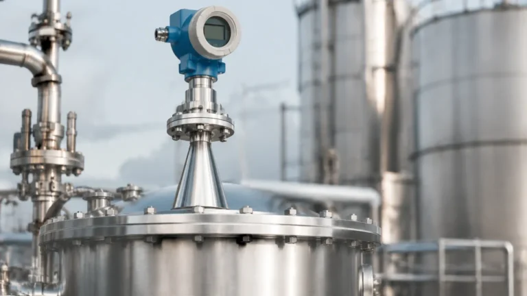
Before selecting a system with a remote indicator, it is vital to understand how the primary sensor functions. Radar level transmitters utilize electromagnetic waves, typically in the microwave frequency range, to measure the distance between the sensor and the surface of the medium.
Time of Flight (ToF) vs. FMCW
Most industrial radar transmitters operate on one of two principles:
1. Pulse Radar (Time of Flight): The transmitter emits a short microwave pulse. This pulse travels to the surface of the medium, reflects, and returns to the receiver. The instrument measures the time elapsed (nanoseconds) and calculates the distance based on the speed of light. Pulse radar is known for its low power consumption and suitability for standard liquid storage.
2. Frequency Modulated Continuous Wave (FMCW): The transmitter emits a continuous signal with a constantly changing frequency. The difference in frequency between the emitted signal and the reflected signal is proportional to the distance. FMCW technology, particularly at higher frequencies like 80GHz, offers significantly higher accuracy (up to ±1mm) and better signal-to-noise ratios, making it ideal for solids, powders, and turbulent liquids.
The Role of Frequency
* 26GHz Radar: Offers a balance between cost and performance. It has a wider beam angle (typically 8° to 20°), which requires careful installation to avoid internal tank obstructions.
* 80GHz Radar: Features a much narrower beam angle (as low as 3°). This allows the signal to avoid heating coils, agitators, and narrow nozzles, providing a much cleaner signal return even in complex vessel geometries.
2. Integrating the Remote Indicator
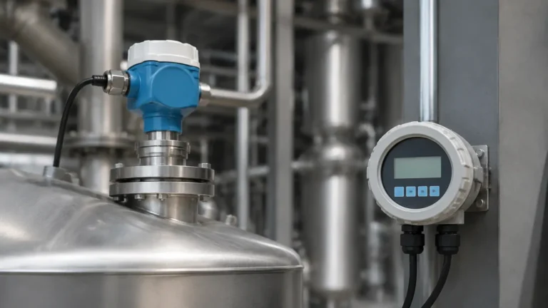
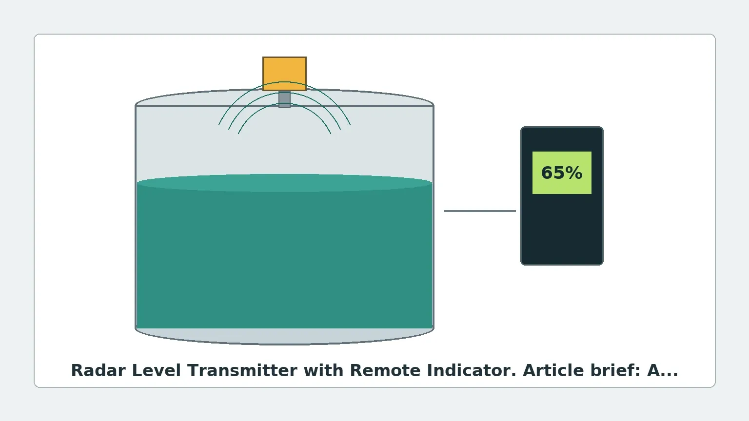
A radar level transmitter with remote indicator consists of two primary components: the sensor (the radar head) and the secondary display unit (the indicator). This configuration is often referred to as a "split-type" level meter.
Why Use a Remote Indicator?
* Safety: In applications involving toxic or high-pressure media, operators can view level data from a safe distance without climbing to the top of the tank.
* Accessibility: If the sensor is installed 20 meters (approx. 65 feet) high on a silo, a remote indicator installed at eye level (1.5 meters) allows for quick routine checks.
* Environmental Protection: While the radar head is designed for process conditions (high temperature/pressure), the indicator can be placed in a controlled environment to extend its lifespan.
* Redundancy and Control: Many remote indicators include integrated relays or 4-20mA retransmission, allowing them to act as local controllers for pumps or alarms independently of the main PLC/DCS.
Communication Protocols
The connection between the transmitter and the remote indicator typically follows industrial standards:
* 4-20mA HART: The most common analog standard. The indicator is often loop-powered, meaning it draws power from the same two wires used for signal transmission.
* RS485/Modbus: A digital protocol that allows for longer transmission distances (up to 1,200 meters) and the ability to transmit multiple parameters (level, volume, signal strength) simultaneously.
3. Selection Criteria and Technical Specifications
Choosing the right combination of radar and indicator requires a detailed analysis of the process environment. The following table provides a comparison of common radar types used in split-type configurations.
Table 1: Radar Level Transmitter Selection Matrix
| Feature | 26GHz Pulse Radar | 80GHz FMCW Radar | Guided Wave Radar (GWR) |
| :— | :— | :— | :— |
| Accuracy | ±3mm to ±5mm | ±1mm to ±2mm | ±2mm |
| Max Range | 30 Meters | 120 Meters | 30 Meters (Cable/Rod) |
| Beam Angle | 8° – 20° | 3° – 8° | N/A (Contact-based) |
| Medium Type | Liquids, Simple Solids | Fine Powders, Corrosives | Low Dielectric Liquids |
| Remote Indicator | Optional (4-20mA/HART) | Standard (Digital/Analog) | Optional (4-20mA/HART) |
| Best Use Case | General storage tanks | Narrow silos, high-precision | Small tanks with foam/steam |
Key Considerations for the Remote Indicator Unit
When specifying the remote indicator, engineers should confirm:
1. Enclosure Rating: For outdoor use, IP65 or IP67 is mandatory. In explosive atmospheres, the indicator must have ATEX or IECEx certification (Intrinsically Safe or Explosion-Proof).
2. Display Type: LED displays offer high visibility in dark areas, while LCD displays provide more detailed information (such as bar graphs and diagnostic codes) and consume less power.
3. Power Supply: Determine if the indicator will be powered by the 24V DC loop or if it requires a separate 220V AC or 110V AC supply.
4. Installation Considerations and Constraints
Correct installation is critical to prevent "false echoes" and ensure the longevity of the radar level transmitter with remote indicator.
Mounting the Radar Sensor
* Nozzle Height: The radar antenna should ideally extend beyond the bottom of the mounting nozzle to prevent signal interference from the nozzle walls.
* Positioning: Avoid mounting the sensor in the center of a domed tank, as this can cause multiple reflections. The ideal position is usually 1/6th of the tank diameter from the wall.
* Obstructions: Ensure the signal path is clear of ladders, pipes, or agitator blades. If obstructions are unavoidable, use a radar with a narrower beam angle (80GHz) or utilize the "False Echo Suppression" software feature found in Welk instruments.
Wiring the Remote Indicator
* Shielding: Use shielded twisted-pair cables for the signal line to prevent Electromagnetic Interference (EMI) from nearby high-voltage equipment or motors.
* Distance Limits: For 4-20mA signals, the distance between the transmitter and indicator should generally not exceed 500 meters without a signal booster. For Modbus RS485, distances can reach 1,200 meters.
* Grounding: Ensure the system is grounded at a single point to avoid ground loops, which can introduce noise into the level reading.
5. Limitations and Application Risks
While radar technology is highly versatile, certain conditions can impact performance:
* Dielectric Constant (εr): Radar relies on the reflection of waves. Materials with a very low dielectric constant (e.g., liquid nitrogen, certain dry powders) reflect very little energy. In these cases, a Guided Wave Radar or a high-sensitivity 80GHz FMCW unit is required.
* Heavy Foam: Dense, thick foam can absorb the radar signal, resulting in a loss of echo. If the foam is conductive, the radar may measure the top of the foam instead of the liquid level.
* Turbulence and Steam: While radar is generally unaffected by steam, extreme turbulence can scatter the signal. Using a stilling well or bypass chamber can mitigate this issue.
* Dust Accumulation: In solid applications (e.g., cement silos), heavy dust can accumulate on the antenna. Selecting a model with a PTFE lens cover or an air-purge connection helps maintain signal integrity.
6. Frequently Asked Questions (FAQs)
Q: Can a remote indicator be used with any radar level transmitter?
A: Not necessarily. The indicator must be compatible with the output signal of the transmitter (e.g., 4-20mA, HART, or Modbus). It is always recommended to source the transmitter and indicator from the same manufacturer, such as Welk, to ensure seamless integration.
Q: How do I calibrate a radar level transmitter with a remote indicator?
A: Most modern units allow for "dry calibration." You input the tank height (Zero point) and the maximum fill level (Full point) via the remote indicator's keypad or a connected laptop. Physical filling of the tank is often unnecessary for the initial setup.
Q: What is the maintenance requirement for these systems?
A: Radar units are virtually maintenance-free because they have no moving parts. However, periodic inspection of the antenna for buildup and checking the wiring connections of the remote indicator is recommended every 6 to 12 months.
Q: Is it possible to connect multiple radar transmitters to a single remote indicator?
A: Yes, if using a multi-channel digital indicator or a Modbus-based system. This allows an operator to toggle between different tanks on a single display screen.
7. Conclusion
The implementation of a radar level transmitter with remote indicator provides a robust solution for complex industrial level measurement tasks. By understanding the nuances of radar frequency, the requirements of signal transmission, and the specific constraints of the process environment, engineers can deploy systems that enhance both operational efficiency and site safety. For high-stakes applications, consulting with a professional manufacturer like Welk ensures that the selected instrumentation meets the rigorous demands of modern industrial automation.
Download Radar Level Transmitter with Remote Indicator as a PDF