Ls Ut
Ls Ut
In the field of industrial process control, the term ls ut—frequently used as shorthand for Level Sensor Ultrasonic Transmitters—represents one of the most versatile and widely adopted technologies for non-contact level measurement. As industries move toward greater automation and precision, understanding the operational mechanics, selection criteria, and installation nuances of these instruments is essential for plant engineers and system integrators.
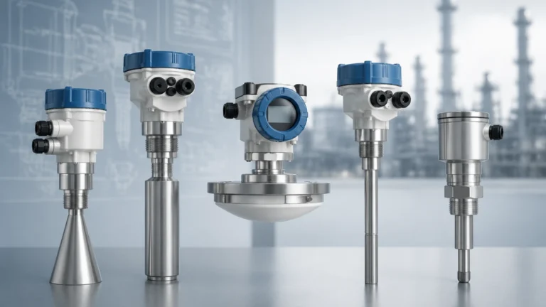
Welk, a professional manufacturer of industrial level measurement instruments, provides a comprehensive range of ultrasonic solutions designed to meet the rigorous demands of water treatment, chemical processing, and oil and gas applications. This guide serves as a practical engineering reference for evaluating and deploying ultrasonic transmitter technology in diverse industrial environments.
Measurement Principles of Ultrasonic Transmitters
Before selecting an ls ut device, it is critical to understand the physics of ultrasonic measurement. These sensors operate on the "Time of Flight" (ToF) principle.
The Time of Flight Mechanism
The sensor's transducer emits a series of high-frequency ultrasonic pulses (typically ranging from 20 kHz to 70 kHz). These sound waves travel through the air or gas space above the medium, strike the surface of the material, and reflect back toward the sensor. The electronic circuitry within the transmitter measures the time interval between the emission of the pulse and the reception of the echo.
Using the known speed of sound in air, the distance ($D$) to the material surface is calculated using the formula:
$$D = \frac{c \times t}{2}$$
Where:
* $c$ is the speed of sound (approximately 344 m/s or 1,128 ft/s at 20°C).
* $t$ is the total travel time for the pulse to go and return.
Since the height of the vessel ($H$) is a known constant, the level of the material ($L$) is determined by subtracting the measured distance from the total height ($L = H – D$).
Temperature Compensation
The speed of sound is not constant; it varies significantly with air temperature. For every degree Celsius change, the speed of sound changes by approximately 0.6 m/s. To maintain accuracy, modern ls ut units from Welk include integrated temperature sensors that provide real-time compensation for these atmospheric changes, ensuring the measurement remains reliable even in outdoor tanks subject to diurnal temperature shifts.
Key Evaluation Criteria for LS UT Selection
Selecting the correct ultrasonic transmitter requires a detailed analysis of the application environment. Failure to account for chemical compatibility or physical constraints can lead to signal loss or premature sensor failure.
1. Measurement Range and Dead Zone
Every ultrasonic sensor has a minimum distance it cannot measure, known as the "Dead Zone" or "Blocking Distance." This is the area immediately below the transducer face where the crystal is still vibrating from the pulse emission and cannot yet "listen" for an echo. If the liquid level enters this zone, the reading will become erratic or lock at a fixed value.
2. Process Media Characteristics
Ultrasonic waves reflect best off hard, flat surfaces. While most liquids provide an excellent reflective surface, certain conditions can interfere with the signal:
* Foam: Heavy, thick foam can absorb ultrasonic energy, preventing an echo from returning to the sensor.
* Vapor and Steam: High concentrations of steam or chemical vapors can alter the speed of sound or cause signal attenuation.
* Turbulence: Rapidly moving or agitated liquid surfaces can scatter the ultrasonic beam, requiring the use of software filtering or a stilling well.
3. Output and Communication
For integration into a Distributed Control System (DCS) or Programmable Logic Controller (PLC), the output signal must be compatible. Common options include:
* 4-20mA Analog: The industry standard for continuous level monitoring.
* HART Protocol: Allows for digital communication over the analog loop for remote configuration and diagnostics.
* RS485/Modbus: Ideal for multi-drop networks and long-distance digital data transmission.
Practical Selection Table
The following table provides a general comparison of typical specifications for industrial ultrasonic level transmitters used in standard applications.
| Feature | Standard Liquid Application | Chemical/Corrosive Application | Long-Range Solids/Liquids |
| :— | :— | :— | :— |
| Measuring Range | 0.4m to 10m (1.3ft to 33ft) | 0.25m to 5m (0.8ft to 16ft) | Up to 30m (98ft) |
| Transducer Material | ABS / Nylon | PVDF / PTFE | Reinforced Composite |
| Accuracy | ±0.25% to 0.5% of span | ±0.2% of span | ±0.5% of span |
| Beam Angle | 8° to 12° | 5° to 9° | 5° to 7° |
| Pressure Limit | Atmospheric (up to 0.3 MPa) | Atmospheric | Atmospheric |
| IP Rating | IP66 / IP67 | IP68 | IP67 |
For more detailed technical data and specific model comparisons, engineers are encouraged to Main Page to review product options and application support.
Installation Considerations and Best Practices
Correct installation is the most significant factor in the long-term performance of an ls ut system. Even the most advanced sensor will fail if the mounting geometry is ignored.
Proper Mounting Location
* Avoid the Center: In cylindrical tanks with arched tops, mounting the sensor in the exact center can create a "parabolic mirror" effect, where multiple echoes converge and confuse the transmitter. It is generally recommended to mount the sensor at 1/2 or 1/3 of the tank radius.
* Clear Path: The ultrasonic beam spreads out in a cone shape (the beam angle). Ensure there are no obstructions within this cone, such as ladders, pipes, or agitator blades. If an obstruction is unavoidable, many Welk transmitters feature "False Echo Suppression" software to ignore fixed internal structures.
* Inlet Proximity: Never install the sensor directly above the tank inlet. Falling material will interfere with the ultrasonic pulse and result in false high-level readings.
Mounting Orientation
The transducer face must be perfectly parallel to the liquid surface. A tilt of even a few degrees can cause the reflected signal to bounce away from the receiver, especially at longer distances. In applications where the sensor is mounted on a nozzle, the height of the nozzle should be kept as short as possible to prevent the ultrasonic pulse from reflecting off the nozzle walls.

Limitations and Risks
While ultrasonic technology is highly cost-effective, it is not a universal solution. Engineers must be aware of the following technological boundaries:
1. Vacuum Conditions: Ultrasonic waves require a gaseous medium (usually air) to travel. They cannot function in a vacuum. For vacuum distillation or similar processes, radar level meters are the preferred alternative.
2. High Pressure: As pressure increases, the density of the gas changes, which can affect the transducer's ability to vibrate efficiently and alter the speed of sound beyond the capabilities of standard compensation algorithms.
3. Heavy Dust: In dry bulk solids applications, excessive dust during filling can attenuate the signal. While high-power ultrasonic sensors exist for solids, radar is often more reliable in extremely dusty environments.
4. Extreme Temperature: Standard ultrasonic transducers are typically limited to process temperatures below 80°C (176°F). High temperatures can damage the piezoelectric crystals or the bonding agents used in the transducer construction.
Frequently Asked Questions (FAQs)
Q: Can an ls ut sensor be used to measure the level of acids or corrosive chemicals?
A: Yes, provided the transducer is constructed from chemically resistant materials like PVDF or PTFE. It is also important to ensure the housing is sealed against corrosive vapors.
Q: What is the difference between a 2-wire and a 4-wire ultrasonic transmitter?
A: A 2-wire transmitter uses the same pair of wires for both power and the 4-20mA output signal, making it easier to install. A 4-wire transmitter has separate pairs for power (often AC or high-voltage DC) and signal, which allows for higher-power pulses and is often used for long-range measurements or when integrated relays are required.
Q: How does wind affect outdoor ultrasonic level measurement?
A: Strong crosswinds can "blow" the ultrasonic pulse away from the receiver or cause turbulence in the air, leading to signal instability. In very windy environments, a stilling well or a protective shroud may be necessary.
Q: Can I shorten the dead zone?
A: The dead zone is a physical property of the transducer design. It cannot be shortened via software. If the liquid level must come very close to the top of the tank, the sensor should be mounted on a stand-off pipe to move the dead zone above the maximum fill level.
Conclusion
The ls ut (Level Sensor Ultrasonic Transmitter) remains a cornerstone of modern industrial instrumentation due to its non-contact nature, lack of moving parts, and ease of maintenance. By understanding the core principles of sound propagation and adhering to strict installation guidelines, facilities can achieve highly accurate and repeatable level data.
Welk continues to lead the industry by providing robust, high-performance ultrasonic solutions tailored to specific process challenges. Whether you are managing a municipal wastewater facility or a complex chemical plant, selecting the right technology is the first step toward operational excellence. For further assistance in selecting the ideal instrument for your specific parameters, please visit the Main Page to explore our full range of level measurement technologies.