Thermal Flow Sensor
Thermal Flow Sensor
In the landscape of industrial process control, the ability to accurately measure the movement of gases is as critical as monitoring the contents of a storage vessel. While level measurement technologies—such as radar, ultrasonic, and hydrostatic sensors—provide data on volume and inventory, the thermal flow sensor serves as the primary tool for quantifying the mass flow rate of gases and, in some specialized cases, liquids. This guide explores the engineering principles, selection criteria, and installation requirements for thermal flow sensors, providing a technical foundation for their integration into industrial automation systems.
Understanding the Measurement Principle
A thermal flow sensor, often referred to as a thermal mass flow meter (TMFM), operates based on the thermal properties of the fluid being measured. Unlike mechanical flow meters that measure volume at line conditions, thermal sensors measure mass flow directly. This is a significant advantage because gas volume changes drastically with temperature and pressure, whereas mass remains constant.
The Physics of Heat Transfer
The fundamental principle relies on the fact that a moving fluid will carry heat away from a heated object. In a typical industrial thermal flow sensor, two Resistance Temperature Detectors (RTDs) are placed within the flow stream.
1. The Reference Sensor: This RTD measures the actual temperature of the process fluid.
2. The Active (Heated) Sensor: This RTD is heated to a specific temperature above the reference sensor.
As the gas flows past the heated sensor, molecules carry heat away from the surface. The rate of this heat loss is directly proportional to the mass flow rate of the gas. There are two primary electronic methods used to translate this heat loss into a flow reading:
* Constant Temperature Differential: The electronics maintain a constant temperature difference ($ΔT$) between the two sensors. As flow increases and more heat is dissipated, more electrical power is required to maintain that $ΔT$. This power consumption is converted into a mass flow signal.
* Constant Current/Power: A fixed amount of power is supplied to the heated sensor. As the flow rate increases, the temperature of the sensor drops. The resulting change in temperature difference ($ΔT$) is measured and correlated to the flow rate.
Because the sensor responds to the heat capacity and thermal conductivity of the gas molecules, the measurement is inherently a mass flow measurement, eliminating the need for separate temperature and pressure compensation in most applications.
Key Advantages in Industrial Applications
The adoption of the thermal flow sensor across industries like water treatment, chemical processing, and oil and gas is driven by several distinct technical benefits:
* No Moving Parts: Unlike turbines or paddlewheels, thermal sensors have no mechanical components that can wear out or seize. This significantly reduces maintenance requirements and increases reliability in harsh environments.
* High Turndown Ratio: These sensors are exceptionally sensitive to low velocities. They can often achieve a turndown ratio of 100:1 or higher, allowing for accurate measurement from very low flow rates (leak detection) to high-speed process flows.
* Direct Mass Flow: By measuring mass rather than volume, engineers avoid the complexities of calculating "Standard Cubic Meters" (Sm³) or "Normal Cubic Meters" (Nm³) manually, as the instrument provides these values directly.
* Low Pressure Drop: Because the sensors are typically small probes inserted into the pipe (insertion style) or have a clear-bore design (in-line style), they introduce negligible resistance to the flow.
Selection Criteria and Technical Specifications
Choosing the correct thermal flow sensor requires a detailed understanding of the process conditions. Unlike level measurement, where the dielectric constant or density might be the primary concern, flow measurement depends heavily on the specific heat of the gas.
1. Gas Composition
Thermal flow sensors are calibrated for specific gases or gas mixtures (e.g., Nitrogen, Compressed Air, Natural Gas, or Biogas). Because every gas has a unique thermal conductivity, a sensor calibrated for Air will not provide accurate readings for Hydrogen without recalibration or the application of a conversion factor. For complex mixtures, such as flare gas, the exact percentage of each component must be known.
2. Flow Range and Pipe Size
Sensors are available in two main configurations:
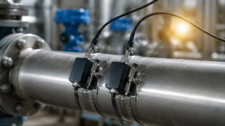
* Insertion Style: Ideal for larger pipes (typically DN50 / 2" and larger). The probe is inserted through a flange or a compression fitting.
* In-Line Style: Used for smaller pipes (typically DN15 to DN50). The sensor is built into a spool piece with defined dimensions to ensure a stable flow profile.
3. Process Temperature and Pressure
Standard thermal flow sensors can typically handle temperatures up to 200°C (392°F) and pressures up to 40 bar (580 psi). High-temperature versions are available for specialized flue gas or combustion air applications.
Comparison Table: Thermal Flow vs. Other Technologies
| Feature | Thermal Flow Sensor | Vortex Flow Meter | Differential Pressure (DP) |
| :— | :— | :— | :— |
| Primary Measurement | Mass Flow | Volumetric Flow | Volumetric Flow |
| Moving Parts | None | None | None |
| Low Flow Sensitivity | Excellent | Poor | Poor |
| Pressure Drop | Very Low | Medium | High |
| Gas Composition | Sensitive | Insensitive | Insensitive |
| Ideal Application | Clean Gas / Compressed Air | Steam / High Velocity Gas | Clean Liquids / Gases |
Installation Considerations
To ensure the accuracy of a thermal flow sensor, the flow profile at the point of measurement must be fully developed and laminar. Turbulence caused by valves, elbows, or reducers will lead to erratic readings.
Straight Pipe Run Requirements
A general rule for insertion thermal flow sensors is to provide a minimum of 20 diameters (20D) of straight pipe upstream and 10 diameters (10D) downstream. If the upstream piping includes a double elbow or a pressure regulator, these requirements may increase to 30D or 40D. If space is limited, flow conditioners (perforated plates) can be used to artificially stabilize the flow.
Orientation and Moisture
In gas applications, moisture is the primary enemy of the thermal flow sensor. If water droplets strike the heated sensor, they cause a rapid cooling effect that the electronics interpret as a massive spike in flow. To mitigate this:
* Install the sensor in a horizontal pipe run.
* Position the sensor at the "10 o'clock" or "2 o'clock" position to avoid condensate pooling at the bottom of the pipe or rising bubbles in a liquid-filled pipe.
* Ensure the gas is above its dew point if possible.
Synergies with Level Measurement Systems
In many industrial setups, flow and level measurements are used in tandem to provide a complete picture of process efficiency. For example, in a chemical dosing system, a hydrostatic level transmitter monitors the remaining volume in a reagent tank, while a thermal flow sensor monitors the nitrogen blanketing gas used to prevent oxidation.
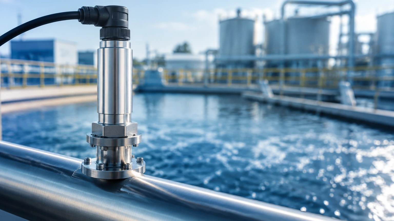
In water treatment facilities, ultrasonic level sensors monitor the height of water in aeration basins, while thermal mass flow meters control the amount of air being pumped into those basins to support biological processes. For engineers seeking a comprehensive suite of industrial instrumentation, including radar and ultrasonic solutions for tank management, visiting the Main Page provides a complete overview of compatible measurement technologies.
Limitations and Risks
While highly versatile, the thermal flow sensor is not a universal solution. Engineers should be aware of the following limitations:
* Coating and Contamination: If the process gas is "dirty" or contains oils, a film may build up on the sensor probes. This coating acts as an insulator, slowing the heat transfer and causing the meter to under-read. Regular cleaning intervals are necessary in these environments.
* Moisture Sensitivity: As mentioned, entrained moisture or condensate will cause significant measurement errors. These sensors are best suited for dry gas applications.
* Gas Mixture Changes: If the ratio of gases in a mixture changes (e.g., a shift in the methane-to-CO2 ratio in biogas), the factory calibration becomes invalid. Some advanced sensors allow for field-programming of gas compositions, but this requires accurate secondary data.
Frequently Asked Questions (FAQ)
Q: Can a thermal flow sensor be used for liquids?
A: Yes, but it is less common. Thermal liquid flow switches are frequently used for flow/no-flow detection. For continuous measurement, they are generally limited to low-viscosity, clean liquids where other technologies like electromagnetic meters might not be suitable.
Q: How often does the sensor need recalibration?
A: In clean gas applications (like compressed air), a thermal flow sensor can maintain accuracy for several years. In corrosive or dirty environments, annual verification is recommended. Many facilities perform a "zero-flow check" as a basic field validation.
Q: Does the sensor require a specific mounting direction?
A: Yes. Most sensors have an arrow indicating the required flow direction. Because the sensor relies on the cooling effect across a specific probe geometry, installing it backward will result in significant errors.
Q: What is the impact of changing pressure on the reading?
A: Because it is a mass flow device, the sensor is largely independent of pressure changes. However, extremely high pressures change the density and thermal properties of the gas slightly, so the operating pressure should be specified at the time of order to ensure the calibration curve is optimized.
Conclusion
The thermal flow sensor is an indispensable tool for modern industrial gas management, offering direct mass flow data with high sensitivity and low maintenance. By understanding the underlying physics of heat transfer and adhering to strict installation guidelines regarding straight pipe runs and moisture control, process engineers can achieve highly reliable data. When integrated with robust level measurement solutions, these sensors enable precise control over both the inventory and the movement of critical process media. For further technical specifications on level and flow instrumentation, refer to the product documentation available on the Main Page.