Cond Meter
Cond Meter
In the landscape of industrial process control, the conductivity meter—often referred to as a "cond meter"—serves as a critical diagnostic and monitoring tool. While primarily categorized under analytical instrumentation, conductivity measurement is inextricably linked to level control and interface detection in various liquid-handling applications. For engineers and plant managers, understanding the nuances of conductivity is essential for optimizing water treatment, chemical processing, and clean-in-place (CIP) cycles.
As a professional manufacturer of industrial level measurement instruments, Welk provides comprehensive solutions that often work in tandem with conductivity data to ensure system integrity. This guide explores the principles of conductivity measurement, its integration into level control, and the practical considerations required for selecting and installing a cond meter in a B2B industrial environment.
Fundamental Principles of Conductivity Measurement
Conductivity is the measure of a solution's ability to conduct an electrical current. This ability is directly proportional to the concentration of dissolved ions (such as salts, acids, or bases) present in the liquid. In pure water, conductivity is extremely low, whereas in concentrated chemical solutions or seawater, it is significantly higher.
The Physics of Ion Movement
When a voltage is applied across two electrodes immersed in a liquid, the ions within the liquid migrate toward the electrodes of opposite polarity. This movement creates an electrical current. The cond meter measures this current and, using Ohm’s Law ($V = I \times R$), calculates the conductance ($G$), which is the reciprocal of resistance ($R$).
To provide a standardized value that is independent of the sensor's physical dimensions, the meter converts conductance into conductivity ($σ$), measured in Siemens per meter (S/m) or, more commonly in industrial settings, microsiemens per centimeter (µS/cm) or millisiemens per centimeter (mS/cm).
The Cell Constant (K)
The geometry of the sensor—specifically the area of the electrodes and the distance between them—defines the "Cell Constant" (K).
- K = 0.1: Used for low conductivity (pure water).
- K = 1.0: Used for medium conductivity (tap water, general process water).
- K = 10.0: Used for high conductivity (wastewater, chemical concentrates).
Types of Cond Meters and Sensors
Industrial conductivity measurement generally falls into two technological categories: Contacting (Electrode) and Inductive (Toroidal).
1. Contacting Conductivity Meters
Contacting sensors feature electrodes that come into direct physical contact with the process fluid. They are highly sensitive and are the preferred choice for low-conductivity applications, such as deionized water or boiler condensate monitoring.
- Two-Pole Sensors: The simplest design, using two electrodes to measure current. They are susceptible to "polarization," where ions build up near the electrode surface, potentially skewing readings at higher concentrations.
- Four-Pole Sensors: These utilize two drive electrodes and two sensing electrodes. This design eliminates the effects of polarization and cable resistance, making them more accurate across a wider range of conductivities.
2. Inductive (Toroidal) Conductivity Meters
Inductive cond meters use two wire-wound metal toroids encapsulated in a plastic or ceramic housing. One coil induces an alternating current in the liquid, and the second coil detects the strength of that current.
- Advantages: Because the sensor is non-contacting (the electrodes are not exposed), it is immune to fouling, coating, and corrosion.
- Applications: Ideal for harsh environments, such as brine, cooling tower blowdown, and heavy chemical processing.
Integrating Conductivity into Level Measurement Systems
Conductivity is frequently used as a method for point-level detection. A conductivity level switch operates by using the liquid itself to complete an electrical circuit between a probe and the tank wall (or a second probe).
When the conductive liquid reaches the probe tip, a small current flows, triggering a relay. This is a robust and cost-effective solution for many water-based applications. For more complex continuous level requirements, engineers often visit the Main Page of specialized manufacturers to compare conductivity switches with radar or ultrasonic technologies, ensuring the chosen method suits the dielectric and conductive properties of the medium.
Key Selection Criteria for Industrial Cond Meters
Selecting the right cond meter requires a detailed analysis of the process fluid and the environmental conditions. The following table provides a comparison to assist in the initial selection process.
| Feature | Contacting (2-Pole) | Contacting (4-Pole) | Inductive (Toroidal) |
| :— | :— | :— | :— |
| Measuring Range | 0.01 µS/cm to 1,000 µS/cm | 10 µS/cm to 500 mS/cm | 100 µS/cm to 2,000 mS/cm |
| Sensitivity | Very High | High | Moderate |
| Fouling Resistance | Low | Moderate | Excellent |
| Chemical Resistance | Depends on electrode material | Depends on electrode material | High (Plastic/Ceramic bodies) |
| Typical Use Case | Ultrapure water | General process water | Acids, bases, wastewater |
Temperature Compensation
Conductivity is highly temperature-dependent. As temperature rises, the viscosity of the liquid decreases, allowing ions to move more freely, which increases conductivity. Most industrial cond meters include an integrated temperature sensor (like a Pt100 or Pt1000) to provide Temperature Compensated readings, usually referenced to 25°C.
Installation Best Practices and Engineering Considerations
To ensure accurate and reliable data from a cond meter, several installation factors must be addressed:
1. Avoid Air Pockets: Sensors should be installed in a location where the liquid is always present and flowing. In horizontal pipes, mount the sensor on the side rather than the top to prevent air bubbles from interfering with the measurement.
2. Full Immersion: The sensing elements must be completely submerged. For inductive sensors, ensure there is sufficient clearance (usually at least 2-3 cm) from the pipe walls to avoid "wall effects" that can distort the electromagnetic field.
3. Grounding and Interference: In environments with heavy electrical machinery, ensure the cond meter is properly shielded and grounded. Electrical noise can interfere with the low-voltage signals generated by conductivity probes.
4. Flow Direction: While many sensors are bi-directional, installing them against the flow can help keep the sensor face clean in applications with suspended solids.
Limitations and Common Operational Risks
While conductivity measurement is a mature and reliable technology, it is not without limitations:
* Non-Conductive Liquids: A cond meter cannot measure the level or concentration of non-polar liquids like oils, hydrocarbons, or pure solvents. In these cases, capacitive or radar level meters are required.
* Scaling and Coating: In contacting sensors, the buildup of calcium or other minerals on the electrodes acts as an insulator, leading to artificially low readings. Regular cleaning or a transition to inductive sensors is necessary in scaling-prone applications.
* High Pressure/Temperature: Standard plastic-bodied sensors may fail in high-pressure steam or high-temperature chemical reactors. Always verify the sensor's pressure and temperature ratings against the maximum possible process excursions.
Maintenance and Calibration Protocols
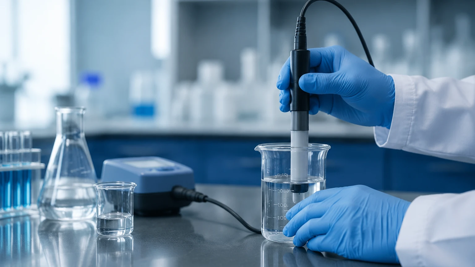
Industrial cond meters require periodic calibration to maintain accuracy.
* Calibration Solutions: Use certified conductivity standards that bracket the expected process range. For example, if measuring cooling water at 500 µS/cm, calibrate using a 1,413 µS/cm standard.
* Cleaning: For contacting probes, use a soft brush or a mild acid dip (depending on the electrode material) to remove deposits. Never use abrasive materials that could change the surface area of the electrodes, as this will alter the cell constant.
* Zero Calibration: Perform a "dry" calibration in the air to ensure the meter reads zero when no liquid is present.
Frequently Asked Questions (FAQ)
Q: Can a cond meter distinguish between different types of chemicals?
A: No. A cond meter measures total conductivity. It cannot distinguish between, for example, Sodium Chloride and Potassium Chloride in the same solution. It only tells you the total ionic strength.
Q: How often should I calibrate my cond meter?
A: This depends on the application. In clean water, once every six months may suffice. In wastewater or chemical dosing, monthly or even weekly checks may be necessary to account for sensor fouling.
Q: What is the difference between conductivity and TDS?
A: Total Dissolved Solids (TDS) is a measure of the mass of dissolved material. Cond meters often estimate TDS by multiplying the conductivity reading by a factor (typically between 0.5 and 0.7). However, this is an approximation and varies by chemical composition.
Q: Why is my reading fluctuating wildly?
A: This is often caused by air bubbles passing through the sensor, improper grounding, or a failing cable connection. Check the physical installation and the integrity of the wiring.
Conclusion
The cond meter is an indispensable component of modern industrial automation, providing the data necessary for both quality control and safety. Whether used for monitoring the purity of boiler feedwater or as a point-level switch in a chemical tank, understanding the underlying principles of ion movement and sensor geometry is key to a successful deployment. For professionals seeking to integrate these sensors into a broader level management strategy, reviewing the technical specifications and product ranges on the Main Page of an established manufacturer like Welk is the recommended next step to ensure the selected technology aligns with specific process demands. By adhering to rigorous installation and maintenance standards, industrial operators can ensure their conductivity measurement systems provide accurate, long-term performance in even the most challenging environments.