Electromechanical Pressure Transducer
Electromechanical Pressure Transducer
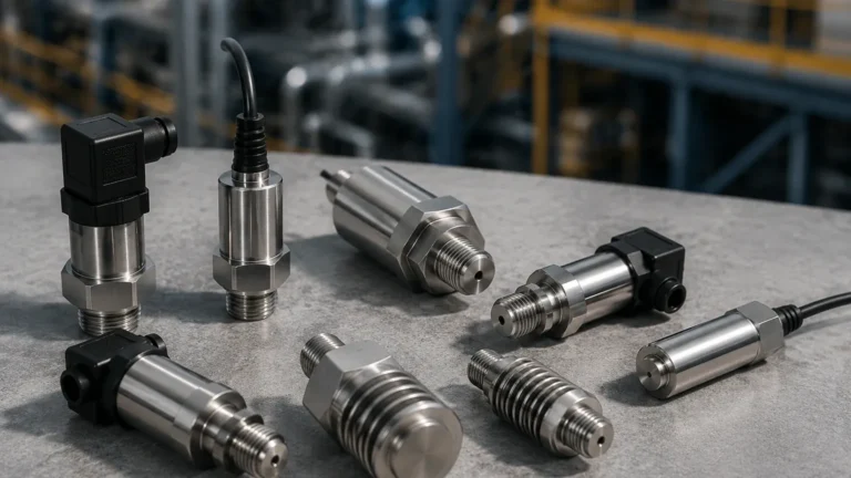
In the landscape of industrial instrumentation, the electromechanical pressure transducer serves as a foundational component for process control and monitoring. These devices are engineered to convert physical pressure—exerted by liquids or gases—into a measurable electrical signal. Within the context of level measurement, particularly hydrostatic level sensing, the electromechanical pressure transducer is the primary mechanism used to determine the height of a fluid column based on its weight.
As industrial processes become increasingly automated, understanding the mechanical-to-electrical conversion process is essential for engineers and plant managers. This guide explores the principles, types, and selection criteria for these transducers, providing a technical reference for their application in demanding environments.
Measurement Principles of Electromechanical Transducers
At its core, an electromechanical pressure transducer consists of two primary functional elements: a mechanical sensing element and an electrical transduction element. The interaction between these two components defines the device's accuracy, sensitivity, and durability.
The Mechanical Sensing Element
The mechanical element is the interface that directly interacts with the process media. When pressure is applied, this element undergoes a physical deformation. Common mechanical structures include:
* Diaphragms: A thin, flexible circular plate (often made of stainless steel or ceramic) that deflects under pressure. This is the most common element in modern industrial transducers.
* Bellows: A thin-walled, convoluted metal tube that expands or contracts axially when pressure changes. Bellows are typically used for lower pressure ranges where greater displacement is required.
* Bourdon Tubes: C-shaped, helical, or spiral tubes that tend to straighten when pressurized. While traditionally used in mechanical gauges, they can be coupled with electrical sensors for high-pressure applications.
The Electrical Transduction Element
The transduction element detects the mechanical displacement or stress in the sensing element and converts it into an electrical change. This change is then processed by internal electronics into a standardized output signal, such as 4-20 mA or 0-10 V. The method of conversion determines the specific category of the electromechanical pressure transducer.
Core Technologies in Electromechanical Transduction
Several technologies are employed to bridge the gap between mechanical force and electrical output. Each offers distinct advantages depending on the application requirements.
1. Strain Gauge Transducers
Strain gauge technology is the most widely utilized method in industrial settings. It relies on the principle of the piezoresistive effect, where the electrical resistance of a conductor changes when it is mechanically strained.
In these devices, strain gauges are bonded to a diaphragm. As pressure deforms the diaphragm, the strain gauges stretch or compress, altering their resistance. These gauges are typically arranged in a Wheatstone Bridge circuit to maximize sensitivity and provide temperature compensation. This technology is robust, highly accurate, and suitable for a vast range of pressures, from vacuum to several thousand bar.
2. Capacitive Transducers
Capacitive transducers measure the change in electrical capacitance between a flexible diaphragm and a fixed backplate. As pressure moves the diaphragm, the distance between the plates changes, varying the capacitance.
These sensors are known for their high sensitivity and ability to measure very low pressures (down to a few millibars). Because they do not require a bonded gauge, they are often more resistant to mechanical shock and can handle significant overpressure without permanent damage.
3. Potentiometric Transducers
These represent a simpler form of electromechanical sensing. A mechanical element, such as a bellows or Bourdon tube, is mechanically linked to a wiper on a variable resistor (potentiometer). As the pressure changes, the wiper moves, changing the resistance in the circuit. While cost-effective and providing a high-level output without complex amplification, they are prone to wear due to the physical contact between the wiper and the resistive element.
4. Linear Variable Differential Transformer (LVDT)
LVDT-based transducers use a non-contact method to measure displacement. The mechanical sensing element moves a ferromagnetic core within a set of primary and secondary coils. The position of the core dictates the voltage induced in the secondary coils. This method is exceptionally durable because there is no friction between the sensing element and the electrical circuit, making it ideal for applications with high vibration or frequent pressure cycling.
Application in Hydrostatic Level Measurement
In the field of level measurement, the electromechanical pressure transducer is the heart of the hydrostatic level transmitter. The principle is based on the relationship between the height of a liquid and the pressure it exerts at the bottom of a vessel:
P = ρ × g × h
Where:
* P is the hydrostatic pressure (Pa).
* ρ (rho) is the density of the liquid (kg/m³).
* g is the acceleration due to gravity (approximately 9.81 m/s²).
* h is the height of the liquid column (m).
By measuring the pressure at a fixed point, and knowing the density of the fluid, the transducer can accurately calculate the level. For industrial tanks, Welk provides specialized hydrostatic solutions that can be found on our Main Page, where various configurations for submersible and externally mounted sensors are detailed.
Technical Selection Criteria
Choosing the correct electromechanical pressure transducer requires a thorough evaluation of the process conditions and the required output. The following table provides a comparison of common technologies used in B2B industrial applications.
Selection Comparison Table
| Feature | Strain Gauge | Capacitive | LVDT | Potentiometric |
| :— | :— | :— | :— | :— |
| Accuracy | High (0.1% to 0.5%) | Very High (0.05% to 0.2%) | Moderate to High | Low to Moderate |
| Pressure Range | Wide (0.1 to 5000+ bar) | Low to Medium | Low to Medium | Medium |
| Durability | High | High | Excellent (Non-contact) | Moderate (Subject to wear) |
| Temperature Sensitivity | Moderate (Requires compensation) | Low | Moderate | Low |
| Cost | Moderate | High | High | Low |
| Common Use Case | General Industrial Process | Laboratory / Low Pressure | High Vibration / Aerospace | Simple Tank Monitoring |
Installation and Engineering Considerations
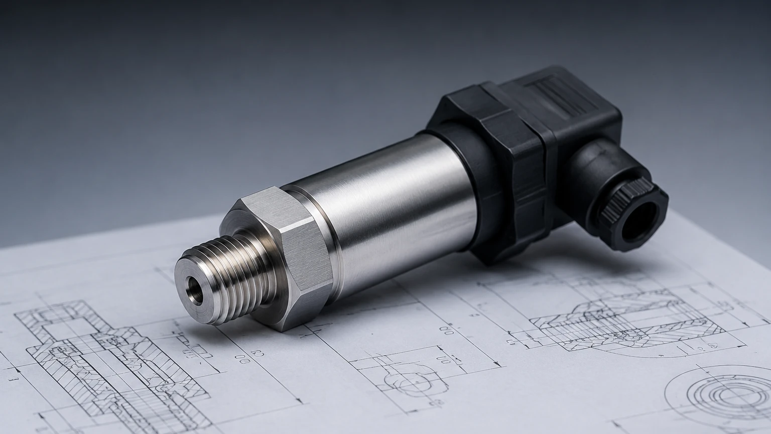
To ensure the longevity and accuracy of an electromechanical pressure transducer, several installation factors must be addressed during the engineering phase.
1. Mounting Position and Orientation
While many transducers can be mounted in any orientation, some (especially low-pressure or capacitive types) may experience a "zero shift" due to the weight of the internal components or the diaphragm itself. It is best practice to calibrate the device in its final mounting position.
2. Atmospheric Referencing
For gauge pressure measurements (pressure relative to atmospheric pressure), the transducer must have a way to "breathe." In submersible level applications, this is achieved through a vented cable containing a small capillary tube. It is critical that this vent remains unobstructed and protected from moisture, as blockages will result in measurement errors corresponding to changes in barometric pressure.
3. Media Compatibility
The wetted materials of the transducer—including the diaphragm and the housing—must be chemically compatible with the process fluid. Standard 316L stainless steel is suitable for water and many oils, but corrosive chemicals may require Hastelloy C, Monel, or Tantalum coatings. For food and beverage applications, hygienic fittings (such as Tri-Clamp) and flush diaphragms are necessary to prevent bacterial growth.
4. Overpressure and Pressure Spikes
In systems with pumps or fast-acting valves, "water hammer" or pressure spikes can occur. These spikes can exceed the burst pressure of the diaphragm. Selecting a transducer with a high overpressure rating (e.g., 2x or 3x the nominal range) or installing a pressure snubber can prevent premature failure.
Limitations and Operational Risks
Despite their reliability, electromechanical pressure transducers are subject to certain physical limitations:
* Hysteresis: The difference in output when approaching a pressure point from a lower pressure versus a higher pressure. High-quality strain gauge and capacitive sensors minimize this effect.
* Long-term Drift: Over time, the electrical components and mechanical sensing elements may undergo subtle changes, causing the "zero" or "span" to shift. Regular calibration (typically annually) is recommended.
* Temperature Effects: Changes in ambient or process temperature can cause materials to expand or contract, affecting the mechanical stress on the sensor. Integrated temperature compensation circuits are vital for maintaining accuracy in outdoor or high-temperature environments.
Frequently Asked Questions (FAQ)
Q: What is the difference between a pressure sensor and a pressure transducer?
A: While the terms are often used interchangeably, a "sensor" generally refers to the sensing element itself, while a "transducer" includes the signal conditioning electronics that convert the raw sensing signal into a standardized electrical output.
Q: Can electromechanical pressure transducers be used in hazardous areas?
A: Yes, but they must be specifically rated (e.g., ATEX, IECEx, or Class/Division) and typically require the use of intrinsic safety barriers or explosion-proof housings.
Q: How do I handle measurement in a sealed tank?
A: In a sealed or pressurized tank, a single pressure transducer at the bottom cannot distinguish between liquid height and the overhead gas pressure. In these cases, a differential pressure (DP) transducer or two separate transducers (one for the bottom and one for the top) must be used to subtract the head pressure.
Q: Why is 4-20 mA the most common output?
A: The 4-20 mA current loop is favored in industrial B2B environments because it is highly resistant to electrical noise and can travel over long distances without signal loss. Additionally, the 4 mA "live zero" allows the system to detect a broken wire (0 mA).
Conclusion
The electromechanical pressure transducer remains a cornerstone of industrial level and pressure measurement. By understanding the mechanical principles of diaphragms and bellows, alongside the electrical characteristics of strain gauges and capacitors, engineers can select the most appropriate technology for their specific application. For a comprehensive range of instruments utilizing these technologies, including radar and ultrasonic alternatives, visit our Main Page to explore our full catalog of measurement solutions. Proper selection, combined with attentive installation and maintenance, ensures these devices provide the accurate data necessary for safe and efficient process operations.