Pressure Transducers
Pressure Transducers
In industrial process control, pressure transducers serve as the fundamental sensing element for a wide array of measurement tasks. While their primary function is to quantify force exerted by a fluid per unit area, their application in level measurement is perhaps one of the most critical roles they play in sectors such as water treatment, chemical processing, and oil and gas. For engineers and procurement specialists, understanding the nuances of how these devices operate and how to select the correct specification is essential for ensuring long-term reliability and accuracy in the field.
Measurement Principles of Pressure Transducers
To effectively implement these sensors, one must first understand the physical principles that allow a pressure reading to be converted into a level measurement. In the context of liquid level, pressure transducers typically operate on the principle of hydrostatic pressure.
Hydrostatic pressure is the pressure exerted by a fluid at equilibrium at a given point within the fluid, due to the force of gravity. The relationship is defined by the formula:
P = ρ × g × h
Where:
* P is the hydrostatic pressure (measured in Pascals or bar).
* ρ (rho) is the density of the liquid (kg/m³).
* g is the acceleration due to gravity (approximately 9.81 m/s²).
* h is the height of the liquid column above the sensor (meters).
Because gravity is constant and the density of the liquid is usually known, the pressure measured by the transducer is directly proportional to the height of the liquid. The transducer utilizes a sensing element—most commonly a piezoresistive silicon sensor or a ceramic thick-film strain gauge—that deforms under the weight of the liquid. This mechanical deformation is converted into an electrical signal, such as 4-20mA, 0-10V, or a digital protocol like HART, which is then interpreted by a PLC or display unit.
For more advanced configurations or to explore specific hardware options, engineers often Review product options and application support on the Welk Main Page to find the right sensor for their specific media.
Types of Pressure Transducers in Level Measurement
Pressure transducers are categorized based on their reference pressure and their physical design. Choosing the wrong type can lead to significant measurement errors, particularly in pressurized tanks or varying atmospheric conditions.
1. Gauge Pressure Transducers
These sensors measure pressure relative to the local atmospheric pressure. They feature a vent tube in the cable or a vent hole in the housing to ensure that changes in barometric pressure do not affect the level reading. These are the standard for open tanks and reservoirs.
2. Absolute Pressure Transducers
Absolute sensors measure pressure relative to a perfect vacuum. These are rarely used for simple level measurement unless the atmospheric pressure is also being monitored separately to calculate the offset, or in specific vacuum-sealed process vessels.
3. Differential Pressure (DP) Transducers
Differential pressure transducers measure the difference between two pressure points. In a closed, pressurized tank, a DP sensor measures the pressure at the bottom of the tank and subtracts the gas-phase pressure at the top. This isolates the hydrostatic pressure of the liquid alone, providing an accurate level reading regardless of the tank's internal pressure.
4. Submersible vs. Externally Mounted
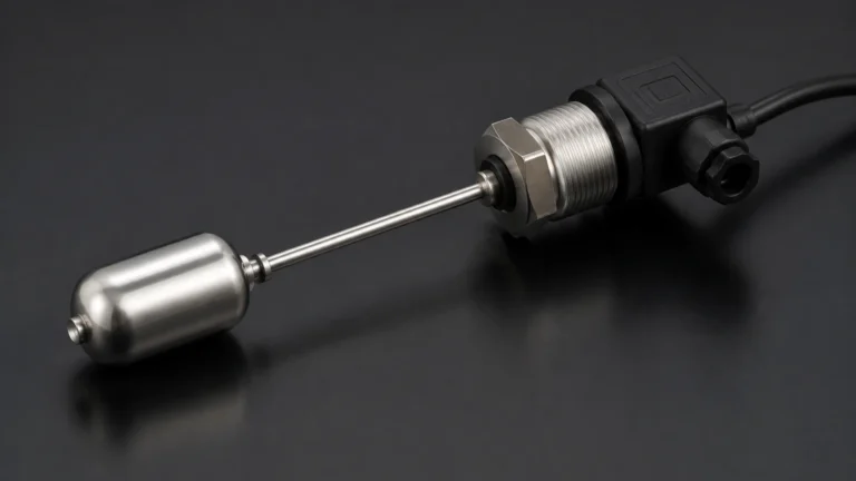
* Submersible Transducers: These are lowered directly into the liquid. They are designed with high ingress protection (IP68) and specialized cable materials (PUR, PE, or FEP) to withstand constant immersion.
* Externally Mounted (Threaded/Flanged): These are installed into a port at the bottom or side of a tank. They are easier to maintain as they do not require entering the vessel, but they require a process connection (e.g., G1/2", NPT, or flange).
Key Evaluation Criteria for Industrial Selection
Selecting pressure transducers for a B2B project requires a rigorous evaluation of the operating environment. The following criteria should serve as a checklist for engineering teams:
* Media Compatibility: The wetted parts (diaphragm and housing) must be chemically compatible with the liquid. While 316L stainless steel is standard, aggressive chemicals may require Hastelloy C, Tantalum, or Ceramic diaphragms.
* Measurement Range: The sensor should be sized so that the maximum expected liquid height falls within 50% to 90% of the transducer's full scale. Over-sizing the range leads to a loss of resolution, while under-sizing risks damaging the sensor during over-pressure events.
* Accuracy and Stability: Industrial applications typically require accuracy of 0.5% FS (Full Scale) or better. Long-term stability (the drift of the signal over time) is equally important to minimize recalibration frequency.
* Temperature Range: Temperature affects both the density of the liquid and the electronics of the sensor. High-quality transducers include internal temperature compensation to maintain accuracy across a range of -20°C to +80°C or higher.
* Output Signal: The industry standard is 4-20mA due to its noise immunity and ability to travel long distances. However, for IoT-integrated plants, Modbus RTU or HART protocols may be preferred.
Practical Selection Table
| Application Type | Recommended Transducer Type | Typical Housing Material | Key Consideration |
| :— | :— | :— | :— |
| Deep Well / Borehole | Submersible Gauge | 304/316L Stainless Steel | Cable tensile strength and lightning protection |
| Pressurized Chemical Tank | Differential Pressure (DP) | Hastelloy C / PTFE Lined | Chemical resistance and static pressure rating |
| Open Water Reservoir | Submersible Gauge | 316L Stainless Steel | Anti-clogging filter and vent tube desiccant |
| Food & Beverage Vessel | Flush Diaphragm (External) | 316L (Polished) | Hygiene standards (3A/EHEDG) and CIP/SIP compatibility |
| Fuel Storage | Submersible / External | 316L / Viton Seals | Explosion-proof (ATEX/IECEx) certification |
Installation Considerations and Best Practices
Even the most accurate pressure transducers will fail if installed incorrectly. Follow these engineering guidelines to ensure optimal performance:
1. Avoid Turbulence: Do not install a submersible transducer directly near an inlet pipe or an agitator. The kinetic energy of moving water can create localized pressure fluctuations. If turbulence is unavoidable, use a "still pipe" (a perforated PVC or steel pipe) to house the sensor.
2. Cable Management: For submersible units, ensure the cable is secured and not subject to chafing. The vent tube inside the cable must remain unobstructed. Use a junction box with a breathable membrane to prevent moisture from entering the vent tube, which can cause internal corrosion.
3. Positioning: The sensor should be located at least 50mm to 100mm above the bottom of the tank or well to prevent it from being buried in silt or sludge, which can block the diaphragm.
4. Zeroing and Calibration: Always perform a zero-point calibration after installation. The weight of the cable or the specific orientation of an external sensor can cause a slight offset that needs to be accounted for in the PLC logic.
Limitations and Common Risks
While pressure transducers are versatile, they are not "set and forget" solutions for every application. Engineers must account for the following limitations:
* Density Sensitivity: Since the measurement is based on weight, any change in the liquid's density (due to temperature changes or mixing of different substances) will result in a level error. If density varies significantly, a secondary compensation method (like a temperature sensor or a second pressure point) is required.
* Clogging: In wastewater or slurries, the small pressure ports or the diaphragm itself can become coated in debris. Flush diaphragm designs are recommended for these environments to prevent buildup.
* Overpressure Events: Hydraulic shock (water hammer) can exert pressures many times higher than the sensor's rating, permanently deforming the diaphragm. Installing a pressure snubber or choosing a sensor with high overpressure protection (e.g., 2x or 3x FS) can mitigate this risk.
* Atmospheric Venting: In gauge pressure sensors, if the vent tube becomes blocked or if moisture enters it, the sensor will show an error that fluctuates with the weather. Regular inspection of desiccant cartridges in the junction box is a mandatory maintenance task.
Frequently Asked Questions (FAQs)
Q: What is the difference between a pressure transducer and a pressure transmitter?
A: In common industrial parlance, the terms are often used interchangeably. Technically, a *transducer* converts pressure into a low-level electrical signal (like millivolts), while a *transmitter* includes additional circuitry to amplify that signal into a standard industrial output like 4-20mA or a digital signal.
Q: How often should pressure transducers be recalibrated?
A: For most industrial applications, an annual calibration check is sufficient. However, in critical chemical processes or high-accuracy water billing applications, a six-month interval may be required. High-quality sensors from reputable manufacturers like Welk often exhibit very low annual drift (<0.1% FS).
Q: Can I use a pressure transducer to measure the level of a dry solid?
A: No. Pressure transducers rely on the fluid properties of liquids to exert equal pressure in all directions. Dry solids do not behave this way; they exert force primarily downward and can "bridge," meaning the pressure at the bottom does not accurately reflect the height of the material. For solids, radar or ultrasonic sensors are preferred.
Q: How do I protect the sensor from lightning strikes?
A: For outdoor installations (reservoirs, dams, boreholes), choose transducers with integrated surge protection. Additionally, ensure the shield of the cable is properly grounded at the control panel and use external surge arrestors on the signal line.
Conclusion for Project Planning
Integrating pressure transducers into an industrial level measurement system requires more than just matching a pressure range. It demands a thorough understanding of the media's chemical properties, the physical dynamics of the vessel, and the long-term maintenance capabilities of the site. By following the principles of hydrostatic measurement and selecting sensors with appropriate materials and protection ratings, engineering teams can achieve highly reliable results.
Before finalizing a project specification, it is advisable to consult the Main Page to compare the latest sensor technologies and ensure that the chosen pressure transducers meet the specific certifications (such as ATEX for hazardous areas or FDA for food grade) required for your industry.