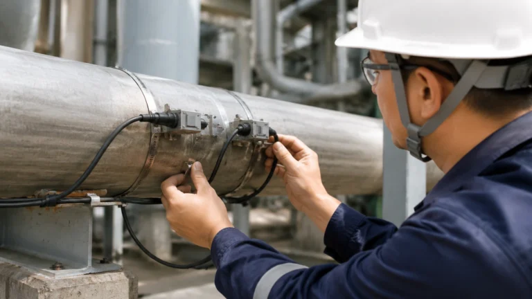
Process Controllers and Analyzers
Process Controllers and Analyzers
In the landscape of modern industrial automation, the synergy between field instrumentation and control systems is the foundation of operational efficiency. Process controllers and analyzers serve as the intelligence layer of an industrial plant, interpreting raw data from sensors to maintain safety, quality, and throughput. For engineers and facility managers, understanding how these components interact—specifically how level measurement data feeds into broader control loops—is essential for optimizing complex processes in water treatment, chemical manufacturing, and the oil and gas sectors.
This guide explores the technical principles of process controllers and analyzers, their integration with level measurement technologies, and the practical considerations required for successful deployment in harsh industrial environments.
Fundamentals of Industrial Process Control
At its core, a process control system is designed to maintain a process variable (such as liquid level, temperature, or pressure) at a desired setpoint. This is achieved through a closed-loop system consisting of three primary elements: the sensor (the eyes), the controller (the brain), and the final control element (the hands, typically a valve or pump).
The Role of Process Controllers
Process controllers, including Programmable Logic Controllers (PLCs) and Distributed Control Systems (DCS), receive signals from field instruments. They apply mathematical algorithms—most commonly Proportional-Integral-Derivative (PID) control—to calculate the necessary adjustment required to minimize the error between the measured value and the setpoint.
The Role of Process Analyzers
While controllers manage the physical state of a process, process analyzers focus on the chemical or physical composition of the media. These instruments provide real-time data on parameters such as pH, conductivity, dissolved oxygen, or hydrocarbon composition. When integrated with level data, analyzers allow for sophisticated control strategies, such as automated chemical dosing based on the volume of liquid currently in a reactor or storage tank.
Level Measurement Principles as Data Inputs
To provide accurate data to process controllers and analyzers, field instruments must utilize measurement principles suited to the specific physical properties of the media. Welk specializes in several core technologies that serve as the primary data source for these systems.
1. Radar Level Measurement
Radar level meters utilize electromagnetic waves to determine the distance to the product surface.
- Principle: Frequency Modulated Continuous Wave (FMCW) or Pulse Radar. The instrument emits a signal, which reflects off the material surface and returns to the sensor. The time-of-flight (ToF) is used to calculate the distance.
- Advantage: Non-contact measurement that is unaffected by changes in temperature, pressure, or vacuum. It is the gold standard for volatile chemicals and high-temperature oil applications.
2. Ultrasonic Level Sensors
Ultrasonic sensors use sound waves rather than electromagnetic waves.
- Principle: The sensor emits an ultrasonic pulse (typically 20 kHz to 200 kHz). The pulse reflects off the surface and the time taken for the echo to return is measured.
- Advantage: Cost-effective for water and wastewater applications where the atmosphere is relatively stable and free of heavy foam or dust.
3. Hydrostatic Level Transmitters
Hydrostatic measurement relies on the relationship between liquid height and pressure.
- Principle: A pressure sensor at the bottom of a tank measures the head pressure exerted by the liquid column. Based on the formula $P = \rho \cdot g \cdot h$ (where $\rho$ is density, $g$ is gravity, and $h$ is height), the level is calculated.
- Advantage: Highly reliable for vented tanks and deep wells, provided the liquid density remains constant.
Integration of Sensors with Process Controllers and Analyzers
For a controller to act on level data, the signal must be transmitted accurately. Modern industrial environments utilize several standardized protocols to bridge the gap between the field and the control room.
* 4-20mA Analog Signals: The most common standard, where 4mA represents 0% (empty) and 20mA represents 100% (full). This current loop is robust against electrical noise over long distances.
* HART Protocol: A digital signal superimposed on the 4-20mA analog loop, allowing for remote configuration and diagnostics of the level meter while the process is running.
* Modbus/RS485: A digital communication protocol often used to link multiple sensors to a single PLC, reducing wiring complexity.
When these signals reach the process controllers and analyzers, they are often combined. For example, in a chemical blending tank, the controller monitors the level (via a radar meter) to prevent overflow, while a process analyzer monitors the concentration of the mixture. If the analyzer detects a concentration drop, the controller may trigger a dosing pump to add more concentrate, while simultaneously adjusting the level setpoint.
To explore the full range of instrumentation compatible with these control architectures, you may review product options and application support on our Main Page.
Selection Criteria for Controllers and Sensors
Choosing the right combination of process controllers and analyzers requires a thorough evaluation of the application environment. The following table provides a general selection framework for level measurement inputs.
| Application Type | Recommended Level Technology | Key Controller Requirement | Common Analyzer Integration |
| :— | :— | :— | :— |
| Water Treatment | Ultrasonic / Hydrostatic | High-speed PID for pump control | pH and Turbidity |
| Chemical Storage | Radar (PTFE Lined) | Intrinsically Safe (IS) barriers | Conductivity / Concentration |
| Oil & Gas | Guided Wave Radar | Redundant I/O for safety | Gas Chromatographs |
| Food & Beverage | Radar (Hygienic) | Batch control logic | Brix / Conductivity |
| Open Channels | Ultrasonic | Flow calculation (Flumes/Weirs) | Dissolved Oxygen |
Practical Selection Considerations
1. Media Characteristics: Does the liquid foam? Is it corrosive? Does the density change? (Density changes affect hydrostatic sensors but not radar).
2. Vessel Geometry: Are there internal obstructions like agitators or heating coils? Radar sensors with narrow beam angles are preferred here.
3. Environmental Conditions: Is there heavy steam or dust? Steam can attenuate ultrasonic signals, making radar a better choice.
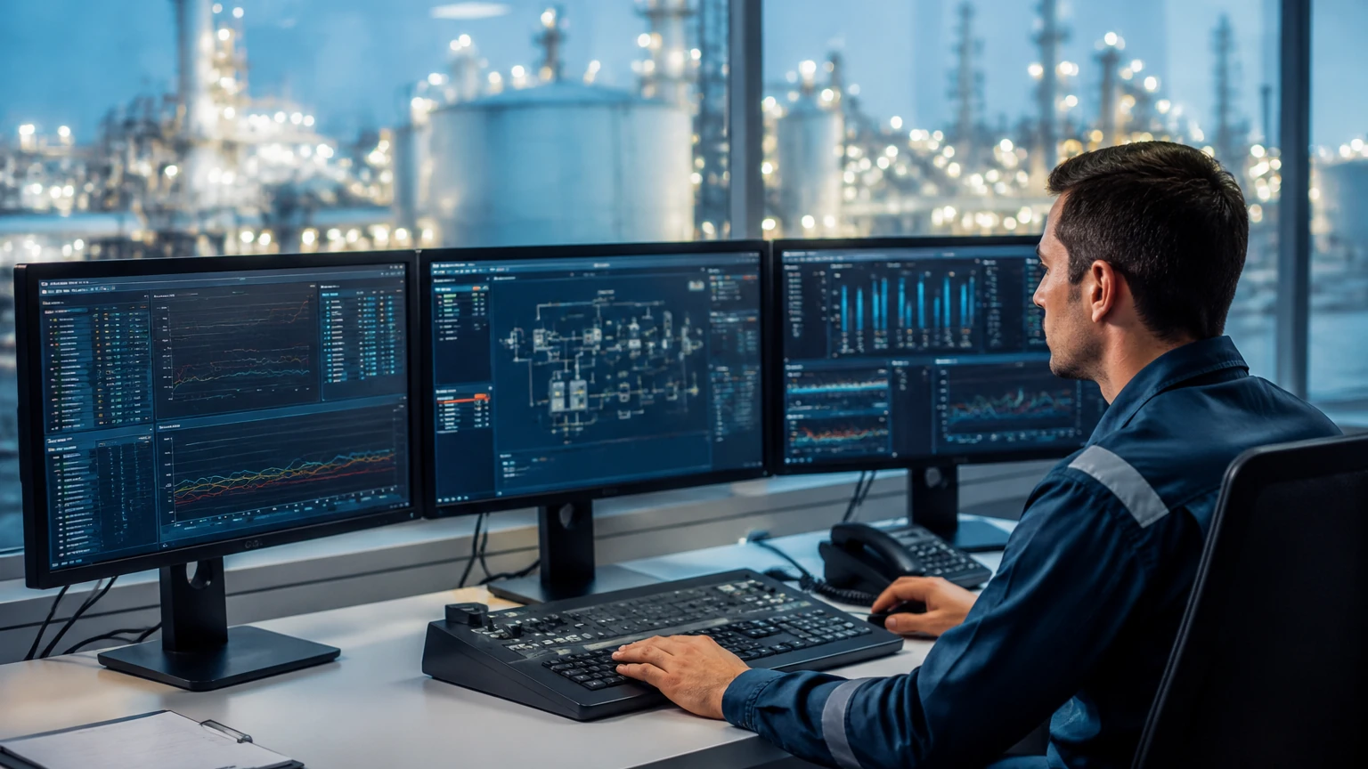
Installation and Integration Best Practices
Even the most advanced process controllers and analyzers will fail if the input data is compromised by poor installation.
Mounting and Positioning
* Avoid the Dead Zone: Every non-contact sensor (radar/ultrasonic) has a "near-field" or dead zone where measurement is impossible. Ensure the sensor is mounted high enough that the maximum liquid level never enters this zone.
* Nozzle Interference: When mounting on a nozzle, ensure the sensor beam does not hit the edge of the nozzle, which creates false echoes.
* Stilling Wells: In tanks with heavy turbulence or foam, installing the level sensor inside a stilling well (a vertical pipe) can provide a calm surface for more accurate measurement.
Wiring and Shielding
To prevent electromagnetic interference (EMI) from variable frequency drives (VFDs) and motors, signal cables must be shielded and grounded at one end (typically the controller end). For 4-20mA loops, twisted-pair cabling is mandatory to maintain signal integrity over distances exceeding 50 meters.
Limitations and Risk Mitigation
While automated systems significantly improve safety, they are not without risks. Engineers must account for the following limitations:
* Signal Lag: In large-scale processes, there is a delay between a control action (opening a valve) and the sensor's response. Controllers must be tuned to account for this "dead time" to prevent oscillation.
* Sensor Fouling: In wastewater or slurry applications, material buildup on the sensor face can lead to signal loss. Non-contact radar is often preferred to minimize maintenance, but regular inspection schedules are still required.
* Power Supply Stability: Process controllers are sensitive to power fluctuations. The use of Uninterruptible Power Supplies (UPS) and surge protection is critical for maintaining control during electrical transients.
Frequently Asked Questions
Q: Can a process controller handle multiple types of level sensors simultaneously?
A: Yes. Most modern PLCs and DCS can accept various inputs (Analog, HART, Modbus). Using two different technologies (e.g., Radar and Hydrostatic) for the same tank is a common practice for "redundancy" in critical safety applications.
Q: How often do process analyzers and level meters need calibration?
A: Level meters like radar are generally stable and may only need verification once a year. However, process analyzers (like pH probes) often require weekly or monthly calibration due to sensor drift and electrode aging.
Q: What is the maximum distance between a sensor and a process controller?
A: For a standard 4-20mA loop, 300 to 600 meters is achievable with high-quality shielded cable. For longer distances, digital protocols or wireless transmitters are recommended.
Q: Is it better to use a standalone controller or a PLC?
A: Standalone controllers are excellent for simple, single-loop tasks (like maintaining one tank level). PLCs are preferred when you need to coordinate multiple sensors, analyzers, and pumps across a larger system.
Conclusion
The integration of reliable level measurement with sophisticated process controllers and analyzers is the cornerstone of modern industrial engineering. By understanding the physical principles of measurement—whether radar, ultrasonic, or hydrostatic—and adhering to rigorous installation standards, facilities can achieve higher levels of precision and safety. As industries move toward more data-driven operations, the accuracy of the field instrument remains the most critical factor in the success of the entire control loop.