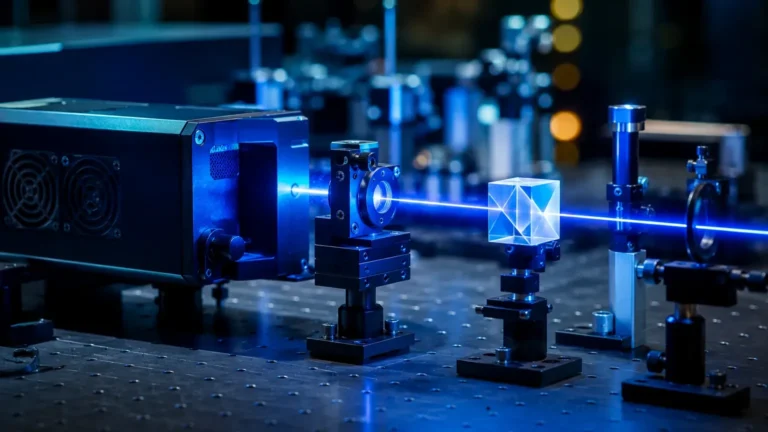
Water Level Controllers
Water Level Controllers
In industrial process automation, water level controllers serve as the critical interface between raw sensor data and mechanical action. These systems are designed to monitor the depth or volume of water within a vessel—ranging from small process tanks to massive reservoirs—and automatically manage pumps, valves, or alarms to maintain the level within specified parameters. For engineers and facility managers, selecting the right combination of sensing technology and control logic is essential for preventing dry-running of pumps, avoiding tank overflows, and ensuring consistent process efficiency.
Effective water level management relies on a closed-loop system: a sensor detects the water level, a controller processes this signal, and an actuator (such as a solenoid valve or a variable frequency drive) adjusts the flow. As a professional manufacturer, Welk provides a range of industrial level measurement instruments that form the foundation of these control systems, ensuring high accuracy and reliability across diverse environmental conditions.
Measurement Principles for Level Control
Before selecting a controller, it is necessary to understand the physics behind the measurement. The input signal to a water level controller typically originates from one of several sensing technologies, each with distinct operational characteristics.
Hydrostatic Pressure Measurement
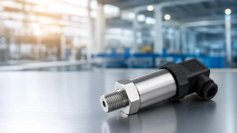
The hydrostatic principle is based on the relationship between the height of a liquid column and the pressure exerted at the base. The formula $P = \rho \cdot g \cdot h$ (where $P$ is pressure, $\rho$ is density, $g$ is gravity, and $h$ is height) allows the sensor to calculate depth. Hydrostatic transmitters are often submersible or mounted to the bottom of a tank. This method is highly effective for deep wells and large vented reservoirs where the liquid density remains constant.
Ultrasonic (Time-of-Flight)
Ultrasonic sensors emit high-frequency sound pulses that reflect off the water surface and return to the transducer. By measuring the time taken for the pulse to return, the sensor calculates the distance to the water. This is a non-contact method, making it ideal for wastewater or corrosive liquids where physical contact might damage the sensor. However, it can be affected by heavy foam, steam, or significant temperature fluctuations that alter the speed of sound.
Radar (Microwave) Technology
Similar to ultrasonic sensors, radar level meters use time-of-flight but employ electromagnetic waves (microwaves) instead of sound. Radar is generally superior in challenging environments because microwaves are unaffected by air temperature, vacuum, high pressure, or dust. High-frequency radar (e.g., 80 GHz) provides a narrow beam angle, allowing for precise measurement even in narrow tanks with internal obstructions like agitators or heating coils.
Conductivity and Float Switches
For simple "on/off" control (point level detection), conductivity probes or magnetic float switches are used. Conductivity probes rely on the electrical conductivity of water to complete a circuit when the water reaches a certain height. Magnetic float gauges use a buoyant element that moves a series of switches or a continuous transmitter as the level rises and falls. These are often used as redundant safety backups for continuous measurement systems.
Key Components of a Water Level Control System
A complete industrial water level controller setup consists of more than just the sensor. To achieve a functional B2B solution, several components must work in unison:
1. The Primary Element (Sensor): This is the radar, ultrasonic, or hydrostatic transmitter that generates a signal (usually 4-20mA, 0-10V, or a digital protocol like Modbus RS485).
2. The Controller/Indicator: This unit receives the sensor signal. It features a digital display to show the current level in meters (m) or millimeters (mm) and contains the logic (such as PID control or simple hysteresis) to trigger outputs.
3. The Final Control Element: These are the actuators, such as motor starters for pumps or electric/pneumatic valves that physically move the water.
4. The Power Supply and Safety Barriers: Industrial systems often require 24V DC power and, in hazardous areas, intrinsic safety barriers to prevent electrical sparks.
Practical Selection Table
Choosing the correct technology depends on the specific requirements of the application. The following table provides a comparison of common sensing technologies used with water level controllers.
| Technology | Accuracy | Range | Contact Type | Best For | Limitations |
| :— | :— | :— | :— | :— | :— |
| Radar | ±1 mm to ±5 mm | Up to 120 m | Non-contact | Precision tanks, steam, foam | Higher initial cost |
| Ultrasonic | ±0.25% of range | 0.5 m – 20 m | Non-contact | Wastewater, open channels | Affected by foam/vapor |
| Hydrostatic | ±0.1% to ±0.5% | 1 m – 500 m | Contact | Deep wells, vented tanks | Sensitive to density changes |
| Magnetic Gauge | ±5 mm to ±10 mm | 0.3 m – 6 m | Contact | High-pressure boilers | Mechanical parts can wear |
| Float Switch | N/A (Point) | Fixed | Contact | Pump start/stop, alarms | Prone to fouling/debris |
Installation Considerations and Best Practices
Proper installation is as critical as selecting the right sensor. Even the most advanced radar level meter will fail if it is poorly positioned. Engineers should follow these guidelines to ensure long-term reliability:
Sensor Positioning
For non-contact sensors (Radar and Ultrasonic), the beam must have a clear path to the water surface. Avoid mounting the sensor directly over the tank inlet, as the turbulence and falling water will cause erratic readings. The sensor should be placed at least 200 mm to 500 mm (8 to 20 inches) away from the tank wall to prevent signal interference from wall reflections.
Dead Zones (Blocking Distance)
Every ultrasonic and radar sensor has a "dead zone" or "blocking distance" near the transducer face where measurement is impossible. Ensure the maximum water level never reaches this zone. If the tank must be filled to the absolute top, a standpipe or nozzle extension may be required to move the sensor further away from the liquid.
Wiring and Signal Integrity
In industrial environments, electrical noise from large motors and variable frequency drives (VFDs) can interfere with the 4-20mA signal. Always use shielded, twisted-pair cables for signal transmission. The shield should be grounded at only one end (usually the controller end) to prevent ground loops. For long-distance transmissions (over 500 meters), digital protocols like Modbus or HART are preferred over analog signals.
Atmospheric Venting
For hydrostatic transmitters, the sensor must be referenced to atmospheric pressure to compensate for changes in weather. This is usually achieved through a small vent tube inside the sensor cable. It is vital to ensure this tube is not kinked, blocked, or exposed to moisture, as this will lead to significant measurement errors.
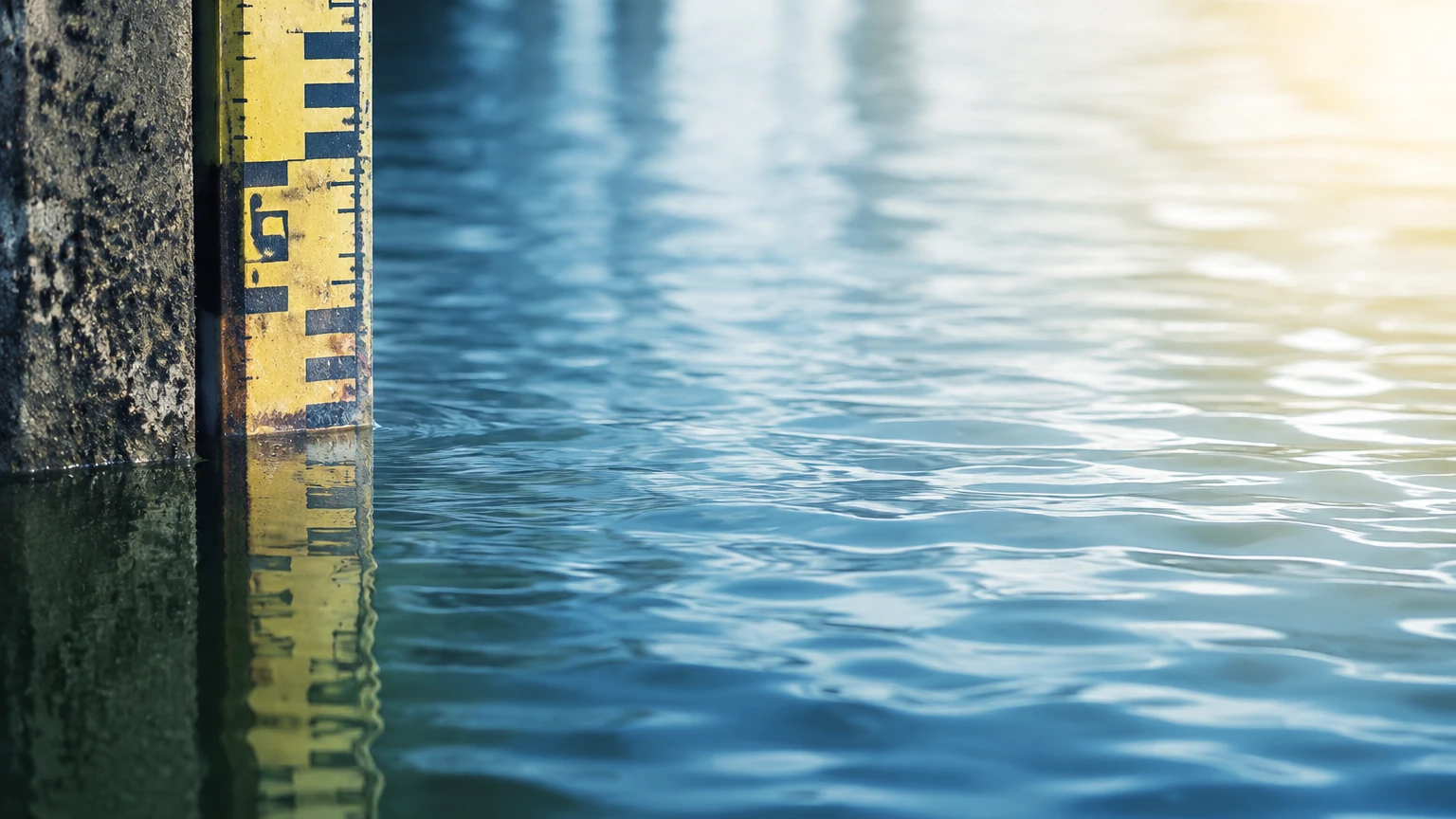
Limitations and Common Risks
While modern water level controllers are robust, they are not immune to failure. Understanding the limitations of each technology helps in designing a more resilient system.
* Foam and Turbulence: Heavy surface foam can absorb ultrasonic signals, leading to a "loss of echo" error. Radar is more resistant but can still be attenuated by very thick, dense foam. In turbulent tanks, a stilling well (a perforated pipe) can be installed to provide a calm surface for the sensor to measure.
* Build-up and Scaling: In hard water or chemical applications, calcium or chemical deposits can build up on the sensor face or float mechanism. This requires regular maintenance or the selection of a non-contact sensor with a self-cleaning flush-mount design.
* Temperature Extremes: High temperatures can cause air density changes (affecting ultrasonic) or physical damage to electronics. Always check the operating temperature range of the sensor and controller. If the process is very hot, consider using a remote-mounted controller or a sensor with a specialized cooling fin or heat sink.
* Power Surges: Industrial sites are prone to lightning strikes and power surges. Without proper surge protection on the input and output lines, the sensitive electronics in the water level controller can be easily destroyed.
Frequently Asked Questions (FAQs)
Q: Can one controller manage multiple tanks?
A: Yes, many multi-channel digital controllers can accept inputs from 2, 4, or even 8 different sensors simultaneously. These are often used in tank farms to centralize monitoring.
Q: How often do water level controllers need calibration?
A: This depends on the technology. Radar and ultrasonic sensors are generally very stable and may only need a verification check once a year. Hydrostatic sensors may require more frequent calibration (every 6 months) if the liquid density or temperature varies significantly.
Q: What is the difference between a level transmitter and a level controller?
A: A transmitter measures the level and sends a signal. A controller receives that signal and makes a decision (e.g., "If level < 2m, then turn on Pump A"). Many modern units combine both functions into a single device.
Q: Is it better to use a top-mounted or bottom-mounted sensor?
A: Top-mounted (non-contact) is generally preferred for ease of maintenance, as you do not need to empty the tank to service the sensor. Bottom-mounted (hydrostatic) is often more cost-effective for very deep or underground applications.
Conclusion and Next Steps
Implementing an effective water level control strategy requires a balance between technical requirements and budget constraints. By understanding the measurement principles—whether it be the precision of radar or the simplicity of hydrostatic pressure—engineers can design systems that ensure safety and operational continuity.
When specifying equipment for your next project, it is important to consult with a manufacturer that offers a comprehensive range of technologies to ensure the solution fits the specific application rather than a one-size-fits-all approach. For detailed technical specifications, product catalogs, and engineering support for your industrial level measurement needs, please visit the Main Page of our official site. Selecting the right water level controllers today prevents costly downtime and equipment failure tomorrow.