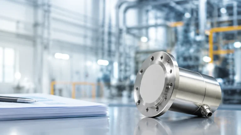
Capacitive Differential Pressure Sensor
Capacitive Differential Pressure Sensor
In the landscape of industrial process control, the capacitive differential pressure sensor stands as a cornerstone technology for measuring flow, level, and pressure. Renowned for its high accuracy and long-term stability, this sensor type is particularly prevalent in demanding environments such as chemical processing, oil and gas refining, and water treatment. For engineers and procurement specialists, understanding the underlying physics and application constraints of these instruments is essential for ensuring process safety and efficiency.
As a leading manufacturer, Welk provides a comprehensive range of industrial level measurement instruments. By integrating advanced sensing technologies, these solutions address the complexities of modern automation. For more information on specific product lines, you can visit our Main Page.
Measurement Principles of Capacitive DP Sensors
The capacitive differential pressure sensor operates on the principle of variable capacitance. The core of the device is a sensing element, often referred to as a "capsule," which contains a central measuring diaphragm and two fixed capacitor plates (electrodes) positioned on either side.
The Capacitance Equation
The fundamental physical principle is defined by the capacitance formula:
$$C = \epsilon \frac{A}{d}$$
Where:
* C is the capacitance.
* ε (epsilon) is the permittivity of the dielectric material between the plates.
* A is the area of the plates.
* d is the distance between the plates.
Sensor Operation
In a capacitive differential pressure sensor, the space between the diaphragm and the fixed plates is filled with an isolating fluid, typically silicone oil or an inert fluorinated oil for oxygen service. When pressure is applied to the high-pressure (H) and low-pressure (L) ports, the pressure is transmitted through isolating diaphragms and the fill fluid to the central sensing diaphragm.
If the pressure on the high side exceeds the pressure on the low side, the central diaphragm deflects toward the low-pressure electrode. This movement decreases the distance ($d$) on the high-pressure side and increases it on the low-pressure side. Consequently, the capacitance on one side increases while the other decreases. The electronic circuitry of the transmitter detects this differential change in capacitance and converts it into a proportional electrical signal, such as a 4-20mA current loop or a digital HART signal.
Advantages of Capacitive Sensing
Compared to piezoresistive or strain-gauge technologies, capacitive sensors offer several distinct advantages:
1. High Sensitivity: They can detect extremely small changes in pressure.
2. Linearity: The differential capacitance change is highly linear over the measuring range.
3. Static Pressure Resistance: Because the sensing diaphragm is protected within a rigid housing and balanced by fill fluid, these sensors exhibit excellent stability even under high static line pressures (up to 40 MPa or 400 bar).
Application in Industrial Level Measurement
One of the primary uses of the capacitive differential pressure sensor is hydrostatic level measurement in tanks. This method relies on the principle that the pressure at the bottom of a liquid column is proportional to the height of the liquid and its density.
Open Tank Measurement
In an open-to-atmosphere tank, the low-pressure side of the sensor is vented to the atmosphere. The high-pressure side is connected to the bottom of the tank. The measured pressure ($P$) is calculated as:
$$P = \rho \cdot g \cdot h$$
Where:
* ρ (rho) is the density of the liquid (kg/m³).
* g is the gravitational acceleration (approx. 9.81 m/s²).
* h is the height of the liquid (m).
Closed and Pressurized Tanks
In pressurized vessels, the pressure above the liquid (the headspace) must be subtracted to determine the true liquid level. The capacitive differential pressure sensor is ideal here; the high-pressure port is connected to the bottom of the tank, and the low-pressure port is connected to the top of the vessel. This configuration cancels out the blanket pressure, leaving only the hydrostatic head of the liquid.
Technical Evaluation and Selection Criteria
Selecting the correct capacitive differential pressure sensor requires a detailed analysis of the process conditions. Failure to account for chemical compatibility or pressure limits can lead to premature sensor failure or measurement drift.
Material Selection Table
| Component | Standard Material | Optional Materials | Application Context |
| :— | :— | :— | :— |
| Isolating Diaphragm | 316L Stainless Steel | Hastelloy C-276, Tantalum, Monel | Corrosive chemicals, acids, and seawater. |
| Fill Fluid | Silicone Oil | Fluorinated Oil, High-Temp Oil | Oxygen service or high-temperature processes. |
| O-Rings | Viton (FKM) | PTFE, Kalrez, Buna-N | Chemical resistance and temperature range requirements. |
| Process Flanges | 316 Stainless Steel | Carbon Steel (Plated), Hastelloy | Structural integrity and external corrosion resistance. |
| Bolting | Stainless Steel | High-tensile Carbon Steel | High-pressure safety requirements. |
Key Performance Specifications
* Turn-down Ratio: This refers to the range over which the sensor can be calibrated without significant loss of accuracy. High-quality capacitive sensors often support turn-down ratios of 100:1.
* Accuracy: Typically expressed as a percentage of the calibrated span (e.g., ±0.075% or ±0.04%).
* Long-term Stability: The ability of the sensor to maintain its calibration over time, often rated as ±0.1% of the upper range limit (URL) over 10 years.
Installation and Commissioning Guidelines
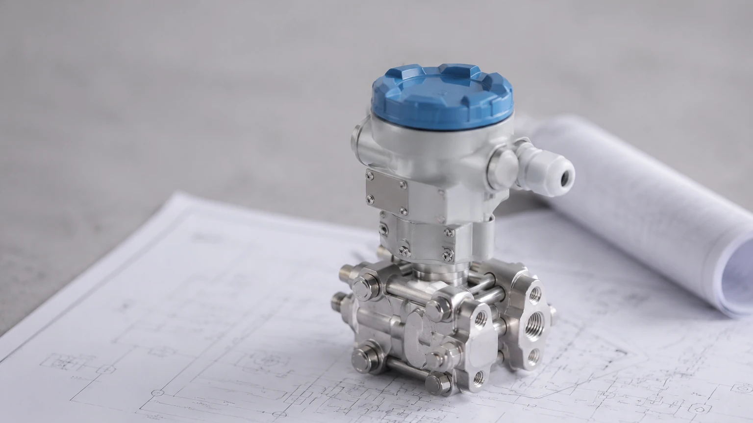
The performance of a capacitive differential pressure sensor is heavily dependent on proper installation. Mechanical stress, temperature gradients, and improper piping can introduce significant errors.
Impulse Piping and Manifolds
For gas or liquid flow and level applications, impulse lines are used to connect the process to the sensor.
1. Slope: Impulse lines should be sloped at least 1:12 (8%) to allow gas bubbles to escape (in liquid service) or condensate to drain (in gas service).
2. Manifolds: A 3-way or 5-way valve manifold is essential. It allows the sensor to be isolated from the process for maintenance and permits "zeroing" the sensor under static pressure by equalizing the high and low sides.
Environmental Protection
While the sensor electronics are typically housed in NEMA 4X or IP67 rated enclosures, extreme temperatures require consideration. In cold climates, impulse lines may need heat tracing to prevent freezing. Conversely, in high-temperature applications, impulse lines provide a cooling effect, protecting the sensor's internal electronics from process temperatures exceeding 85°C (185°F).
Mounting Position
The orientation of the sensor can affect the zero point due to the weight of the fill fluid. It is critical to mount the sensor securely and perform a zero trim after installation to eliminate position-related offsets.
Limitations and Mitigation Strategies
Despite their robustness, capacitive differential pressure sensors have limitations that engineers must mitigate through design.
1. Static Pressure Effects
Although capacitive sensors handle high static pressure well, a small "zero shift" can occur when the system is pressurized. This is a systematic error that can be calibrated out using the manifold to equalize pressure at the operating static pressure level.
2. Temperature Drift
Changes in ambient temperature affect the density and volume of the internal fill fluid, leading to measurement drift. Modern transmitters include internal temperature sensors to provide active compensation, but shielding the instrument from direct sunlight or radiant heat from process pipes is still a best practice.
3. Hydrogen Permeation
In high-pressure hydrogen service, hydrogen molecules can permeate through standard stainless steel diaphragms and dissolve into the fill fluid, forming bubbles that degrade sensor performance. For these applications, gold-plated diaphragms are recommended as an effective barrier.
Comparison: Capacitive vs. Piezoresistive Technology
| Feature | Capacitive DP Sensor | Piezoresistive DP Sensor |
| :— | :— | :— |
| Overpressure Protection | Excellent (Mechanical stops) | Moderate (Diaphragm fatigue) |
| Accuracy | Very High (0.04% – 0.075%) | High (0.1% – 0.25%) |
| Stability | Superior long-term stability | Good, but prone to drift |
| Cost | Higher | Lower |
| Signal Output | Digital/Analog (HART, Profibus) | Mostly Analog |
Frequently Asked Questions (FAQs)
Q: How often should a capacitive differential pressure sensor be calibrated?
A: While many modern sensors offer stability for up to 5 or 10 years, industry standards often recommend a verification check every 12 to 24 months, depending on the criticality of the process and the harshness of the environment.
Q: Can these sensors be used for level measurement in vacuum tanks?
A: Yes. However, special care must be taken regarding the fill fluid. Standard silicone oil may outgas under high vacuum. Engineers should specify a low-vapor-pressure fill fluid and ensure the sensor is mounted below the bottom tap to maintain a positive head on the transmitter.
Q: What is the difference between a "dry leg" and a "wet leg" installation?
A: In closed tank level measurement, if the gas in the headspace condenses, it can fill the low-pressure impulse line. A "dry leg" is used when condensation is unlikely; a "wet leg" is a line intentionally filled with a compatible liquid to provide a constant, known pressure on the low side, preventing errors caused by random condensation.
Conclusion
The capacitive differential pressure sensor remains a premier choice for industrial automation due to its precision and resilience. By understanding the interaction between diaphragm mechanics and electrical capacitance, process engineers can better specify instruments that withstand the rigors of the field. Whether managing water treatment facilities or complex chemical reactors, the integration of reliable DP sensors is a fundamental step toward operational excellence.
For technical support in selecting the right level and pressure instrumentation for your specific project, please consult our engineering resources on the Main Page. Welk is committed to providing accurate, cost-effective, and customized solutions for global industrial applications.