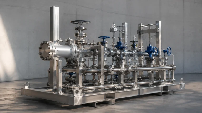
Micropilot Fmr240
Micropilot Fmr240
In the landscape of industrial process automation, radar level measurement has emerged as the preferred technology for challenging liquid applications. The Micropilot FMR240 represents a specific class of high-frequency pulse radar transmitters designed to provide high precision in small-to-medium-sized vessels. As a 26 GHz (K-band) instrument, it addresses the limitations of older 6 GHz technology, offering narrower beam angles and better performance in environments with internal obstructions or agitated surfaces.
For engineers and procurement specialists evaluating level measurement solutions, understanding the underlying physics and application constraints of instruments like the FMR240 is essential for ensuring long-term reliability. This guide examines the technical foundations, selection criteria, and installation best practices for high-frequency pulse radar technology. For a broader overview of available industrial instrumentation, technical professionals may refer to the Main Page for detailed product specifications and application support.
Measurement Principle: Pulse Radar and Time-of-Flight
The Micropilot FMR240 operates on the "Time-of-Flight" (ToF) principle using microwave pulses. Unlike Frequency Modulated Continuous Wave (FMCW) radar, which emits a continuous signal with a varying frequency, pulse radar sends out discrete bursts of microwave energy.
The Physics of Reflection
1. Emission: The instrument’s antenna emits a short microwave pulse (typically around 26 GHz) toward the medium surface.
2. Propagation: The pulse travels through the gas phase (usually air or nitrogen) at the speed of light.
3. Reflection: When the pulse hits the surface of the liquid, a portion of the energy is reflected back toward the antenna. The strength of this reflection depends on the dielectric constant ($ε_r$) of the medium. A higher $ε_r$ results in a stronger return signal.
4. Reception: The sensor’s electronics detect the returning pulse and calculate the time elapsed between emission and reception.
The distance ($D$) from the sensor reference point to the product surface is calculated using the formula:
$$D = \frac{c \times t}{2}$$
Where:
* c is the speed of light.
* t is the measured transit time.
The level ($L$) is then derived by subtracting the distance ($D$) from the total tank height ($E$).
Technical Advantages of 26 GHz Frequency
The choice of a 26 GHz frequency (K-band) provides several distinct advantages over lower-frequency 6 GHz (C-band) radar systems. These advantages are particularly relevant in modern industrial tanks which are often crowded with internal structures.
* Narrower Beam Angle: For a given antenna size, a higher frequency results in a more focused beam. A 26 GHz radar can achieve a beam angle as narrow as 8° with a standard horn antenna, whereas a 6 GHz radar might require a significantly larger antenna to achieve the same focus. This allows the signal to bypass agitators, heating coils, and baffles.
* Smaller Antenna Footprint: High-frequency radar allows for smaller process connections. This is critical for retrofitting older tanks where only small nozzles (e.g., DN50 or DN80) are available.
* Higher Precision: The shorter wavelength of the 26 GHz signal allows for better resolution and accuracy, typically reaching ±3 mm in standard process conditions.
Selection Criteria and Technical Specifications
When selecting a radar transmitter like the Micropilot FMR240, engineers must match the antenna type and material to the process chemistry and physical environment. The following table outlines typical performance characteristics for this class of pulse radar.
Table 1: Typical Performance Specifications
| Feature | Specification Details |
| :— | :— |
| Measuring Range | 0.5 m to 40 m (up to 70 m with specific configurations) |
| Frequency | K-band (~26 GHz) |
| Accuracy | ±3 mm (0.12 in) |
| Process Temperature | -40°C to +200°C (-40°F to +392°F) |
| Process Pressure | Vacuum to 40 bar (580 psi) |
| Min. Dielectric Constant | ε_r ≥ 1.9 (direct) / ε_r ≥ 1.4 (stilling well) |
| Output Signal | 4-20 mA HART, PROFIBUS PA, or FOUNDATION Fieldbus |
Antenna Options
* Horn Antenna: The most common choice for storage and buffer tanks. It is robust and available in various sizes (DN40 to DN100). Larger horns provide narrower beams.
* Parabolic Antenna: Used for very long ranges (up to 70 m) or for media with extremely low dielectric constants, as it provides the highest signal gain.
* PTFE-Clad/Flush Mount: Ideal for corrosive environments or hygienic applications where the antenna must be protected from the process medium.
Installation Best Practices
Correct installation is the most critical factor in the performance of a radar level meter. Even the most advanced signal processing software cannot compensate for a poorly positioned sensor.
Positioning the Transmitter
* Wall Distance: Do not mount the sensor too close to the tank wall. The rule of thumb is to maintain a distance of at least 1/6 of the tank diameter from the wall to avoid interference from wall reflections.
* Avoid the Center: In cylindrical tanks with conical or dished bottoms, do not mount the sensor in the exact center. This can lead to multiple reflections (parabolic effect) that confuse the signal processing electronics.
* Nozzle Geometry: The antenna should ideally extend beyond the bottom of the mounting nozzle. If the nozzle is longer than the antenna, internal reflections within the nozzle can create a "ringing" effect that masks the true level signal near the top of the tank.
Obstruction Management
* Agitators and Baffles: If the tank contains an agitator, the radar should be positioned so the beam does not hit the blades directly. Most modern transmitters include a "False Echo Mapping" or "Envelope Curve" function that allows the user to record and ignore reflections from static internal structures.
* Inflow Streams: Never mount the sensor directly above the filling stream. The turbulence and the stream itself will scatter the radar signal, leading to erratic readings.
Application Suitability and Limitations
While 26 GHz pulse radar is highly versatile, it is not a universal solution for every process. Understanding its limitations is key to successful application engineering.
Where it Excels
* Standard Chemical Storage: Acids, alkalis, and solvents in stainless steel or plastic tanks.
* Water and Wastewater: Level monitoring in basins, pumping stations, and chemical dosing tanks.
* Pharmaceuticals: Small-volume vessels requiring high precision and hygienic connections.
Limitations and Challenges
* Heavy Foam: Radar signals are often absorbed or scattered by thick, dense foam. If a process involves significant foaming, ultrasonic sensors or guided wave radar (GWR) may be more appropriate, depending on the foam density.
* Low Dielectric Media: Non-polar hydrocarbons (like liquefied gases or pure oils) have low dielectric constants ($ε_r < 1.9$). In these cases, the reflection may be too weak for standard free-space radar. A stilling well or bypass pipe can be used to concentrate the signal energy.
* Heavy Condensation/Buildup: If the medium is prone to heavy crystallization or condensation that coats the antenna, the signal may be attenuated. In such cases, a sensor with a PTFE flush-mount antenna or a compressed air purging system should be used.

Troubleshooting Common Issues
When a radar level meter fails to provide a consistent reading, the following steps are typically taken by maintenance personnel:
1. Check the Envelope Curve: Use the device software to view the signal strength. A healthy signal should show a clear peak significantly higher than the noise floor.
2. Verify Dielectric Settings: If the level jumps to the bottom of the tank when the vessel is full, the dielectric constant setting may be too low, causing the device to lose the surface signal.
3. Inspect for Build-up: Physically check the antenna for coating. Even a thin layer of conductive material can short-circuit the signal transmission.
4. Re-map False Echoes: If a new internal structure has been added to the tank, the false echo map must be updated to ensure the device ignores the new reflection.
Comparison: Pulse Radar vs. Guided Wave Radar (GWR)
It is common to compare the Micropilot FMR240 with Guided Wave Radar (GWR) instruments. While both use microwaves, GWR uses a physical probe (rod or cable) to guide the signal to the surface.
| Feature | Free-Space Radar (FMR240) | Guided Wave Radar (GWR) |
| :— | :— | :— |
| Contact | Non-contact | Contact (Probe in medium) |
| Maintenance | Very Low | Moderate (Probe cleaning) |
| Foam Performance | Sensitive to foam | Better penetration of foam |
| Installation | Easier (No probe to install) | Requires probe length matching |
| Vessel Geometry | Sensitive to obstructions | Immune to tank internals |
Conclusion
The Micropilot FMR240 and similar 26 GHz pulse radar transmitters offer a robust, non-contact solution for a wide range of industrial level measurement tasks. By leveraging high-frequency microwaves, these devices provide the narrow beam angles and high precision required for modern process control. However, successful implementation requires careful attention to the dielectric properties of the medium and the physical geometry of the vessel.
For engineers seeking to integrate these technologies into their facilities, selecting the right instrument involves balancing performance requirements with budget and installation constraints. To explore a comprehensive range of radar, ultrasonic, and hydrostatic level measurement options, visit the Welk Main Page for technical documentation and expert selection guides.
Frequently Asked Questions (FAQ)
Q: Can the FMR240 measure through plastic tank walls?
A: Yes, because microwaves can penetrate non-conductive materials. However, the signal strength will be reduced, and the dielectric constant of the liquid must be sufficiently high to provide a clear reflection from the other side of the wall.
Q: What is the minimum distance the radar can measure?
A: Most radar sensors have a "blocking distance" or "dead zone" near the antenna, typically between 0.2 m and 0.5 m. Level measurement is not possible within this zone.
Q: How does temperature affect radar measurement?
A: Unlike ultrasonic sensors, radar is largely unaffected by changes in gas temperature, pressure, or vapor composition, as the speed of light is constant in these environments. This makes radar far more reliable for high-temperature process vessels.