Acoustic Level Sensor
Acoustic Level Sensor
In the landscape of industrial process control, the acoustic level sensor—more commonly referred to as an ultrasonic level transmitter—represents one of the most versatile and reliable methods for non-contact level measurement. By utilizing sound waves to determine the distance between a sensor and a medium, these instruments provide a solution that avoids physical contact with the material being measured, thereby reducing maintenance requirements and preventing contamination. This guide provides a comprehensive technical overview of acoustic level measurement technology, its principles, selection criteria, and practical installation considerations for engineering professionals.
Understanding Acoustic Level Measurement Principles
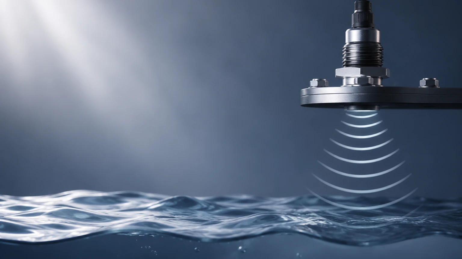
The fundamental operation of an acoustic level sensor is based on the "Time of Flight" (ToF) principle. The device consists of a transducer that acts as both a transmitter and a receiver.
1. Emission: The sensor's transducer emits a high-frequency acoustic pulse (typically in the ultrasonic range of 20 kHz to 70 kHz).
2. Propagation: This sound wave travels through the air or gas space toward the surface of the target medium.
3. Reflection: Upon hitting the surface of the liquid or solid, the acoustic energy is reflected back toward the sensor as an echo.
4. Detection: The transducer receives the reflected echo and converts the mechanical vibration back into an electrical signal.
5. Calculation: The internal electronics calculate the distance ($D$) based on the time delay ($t$) between emission and reception, using the known speed of sound ($c$) in the medium: $D = (c \times t) / 2$.
Because the speed of sound in air is approximately 344 m/s (1,128 ft/s) at 20°C (68°F), but varies significantly with temperature, modern sensors include integrated temperature compensation. This ensures that the level reading remains accurate even as the ambient temperature within the tank fluctuates. For engineers seeking specific product data and technical datasheets for these systems, the Main Page provides a centralized resource for various industrial configurations.
Key Components of an Acoustic Level Sensor System
A robust industrial acoustic level sensor is comprised of several critical sub-assemblies designed to withstand harsh process environments:
* The Transducer: Usually constructed from piezoelectric crystals or specialized ceramics. It must be housed in materials like PVDF, PTFE, or stainless steel to resist chemical corrosion.
* Signal Processing Unit: This is the "brain" of the sensor. It utilizes advanced algorithms to filter out "false echoes" caused by internal tank obstructions like ladders, agitators, or weld seams.
* Housing and Interface: Industrial units typically feature IP66/IP67 or NEMA 4X rated housings. They provide user interfaces for calibration and output signals such as 4-20mA (HART), RS485 (Modbus), or Profibus for integration into PLC and SCADA systems.
Technical Evaluation and Selection Criteria
Selecting the correct acoustic level sensor requires an analysis of the physical and chemical properties of the application. Not all acoustic sensors are suitable for every environment. Use the following criteria to evaluate your needs:
1. Measurement Range
Sensors are designed for specific ranges. A sensor optimized for a 5m (16.4 ft) range will have a different transducer frequency than one designed for a 30m (98.4 ft) range. Generally, lower frequencies are used for longer distances because they attenuate less in air, while higher frequencies offer better resolution for short-range applications.
2. The "Dead Zone" (Blocking Distance)
Every acoustic sensor has a minimum distance requirement directly in front of the transducer face where it cannot measure. This is known as the dead zone or blocking distance. It occurs because the transducer cannot receive an echo while it is still vibrating from the emission pulse. Typical dead zones range from 0.2m (8 in) to 0.8m (31 in) depending on the frequency.
3. Process Environment
* Temperature: Standard sensors operate between -40°C and +80°C. High-temperature variants are available but limited compared to radar technology.
* Pressure: Acoustic sensors are generally limited to near-atmospheric pressures (typically up to 3 bar or 43.5 psi). High pressure increases the density of the gas, significantly altering the speed of sound beyond the limits of standard compensation.
* Vapor and Dust: Heavy steam or dense dust can absorb or scatter sound waves, reducing signal strength.
Selection Table for Industrial Applications
| Feature | Liquid Storage (Standard) | Chemical/Corrosive Tanks | Solids/Grains (Silos) |
| :— | :— | :— | :— |
| Recommended Housing | Plastic (ABS/PC) or Aluminum | PVDF or PTFE Coated | Reinforced Aluminum |
| Typical Frequency | 40 kHz – 50 kHz | 40 kHz | 10 kHz – 20 kHz |
| Mounting Type | Threaded (G/NPT) | Flanged | Aiming Flange (Swivel) |
| Accuracy | ±0.25% of range | ±0.25% of range | ±0.5% to 1% of range |
| Key Concern | Turbulence/Foam | Chemical Compatibility | Dust/Angle of Repose |
Installation and Engineering Best Practices
Correct installation is the most critical factor in ensuring the long-term performance of an acoustic level sensor. Engineers should adhere to the following guidelines:
Beam Angle Awareness
The acoustic pulse is not a laser; it spreads out in a cone shape (typically 5° to 12°). Ensure that there are no obstructions within this cone. If the beam hits a ladder or a pipe, it will return a false high-level reading.
Perpendicular Alignment
The sensor face must be mounted perfectly parallel to the liquid surface. If the sensor is tilted, the sound wave may reflect off the surface at an angle and never return to the transducer, resulting in a "Loss of Echo" (LOE) error.
Avoiding the Fill Stream
Never install a sensor directly above the tank's inlet. The falling liquid or solid will interfere with the acoustic pulse and provide erratic readings.
Standpipe Considerations
If a standpipe (stillpipe) is used to avoid foam or turbulence, the pipe must be smooth and free of burrs. The inner diameter should be large enough to prevent the acoustic beam from reflecting off the pipe walls prematurely.
Limitations and Mitigation Strategies
While the acoustic level sensor is a powerful tool, it has inherent physical limitations that engineers must account for:
1. Vacuum Conditions: Sound requires a medium to travel. Acoustic sensors cannot function in a vacuum.
2. Heavy Foam: Foam acts as a sound absorber. If the foam is thick and light, it may absorb the acoustic pulse entirely, leading to signal loss. In such cases, a magnetic level gauge or a radar sensor may be more appropriate.
3. Variable Gas Mixtures: If the gas space above the liquid is not air (e.g., a heavy concentration of CO2 or Nitrogen), the speed of sound will change. If the gas mixture is inconsistent, the accuracy will degrade unless the sensor is calibrated for that specific gas constant.
4. Surface Turbulence: Rapidly agitating liquids can scatter the echo. This can often be mitigated by using software damping (averaging) or installing a stilling well.
Frequently Asked Questions (FAQs)
Q: Can an acoustic level sensor measure the level of solids?
A: Yes, but with caveats. Solids like grain, sand, or plastic pellets have an "angle of repose" which can deflect the sound wave away from the sensor. For solids, it is recommended to use a sensor with a higher power output and a lower frequency, often mounted on an adjustable flange to aim the sensor at the optimal reflection point.
Q: How does wind or air movement affect the sensor?
A: In outdoor applications, strong winds can "blow" the acoustic pulse away, especially over long distances. For outdoor sumps or open channels, using a sensor with a protective sunshade and ensuring the measurement distance is kept as short as possible helps maintain stability.
Q: Is it possible to use these sensors in hazardous areas?
A: Yes, many acoustic level sensors are available with ATEX, IECEx, or FM certifications for use in Class I, Div 1 or Div 2 environments. These typically feature intrinsically safe electronics or explosion-proof housings.
Q: What is the typical lifespan of an acoustic level sensor?
A: In a well-specified environment (non-corrosive, moderate temperature), these sensors can last 10 to 15 years. The primary failure point is usually the degradation of the transducer face due to extreme chemical exposure or physical impact.
Conclusion
The acoustic level sensor remains a cornerstone of industrial level monitoring due to its non-contact nature and cost-effectiveness. By understanding the relationship between sound propagation and the process environment, engineers can implement highly accurate systems for water, chemical, and bulk solid management.
Before finalizing a system design, confirm the chemical compatibility of the transducer housing, the maximum expected temperature, and the presence of any internal tank obstructions. For a detailed review of available hardware and to consult with application engineers on specific project requirements, please refer to the Main Page for technical support and product selection tools.