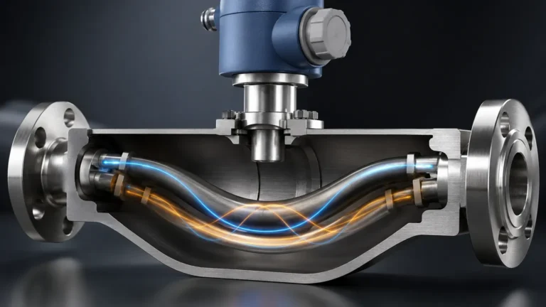
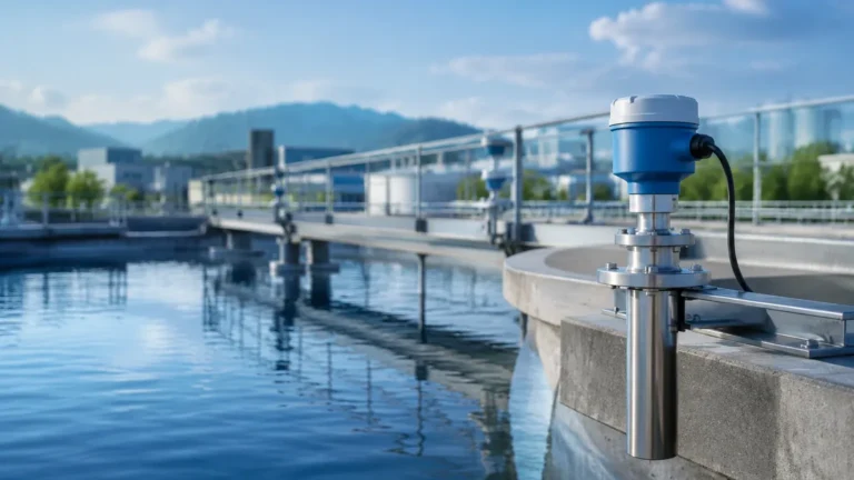
Flare Gas Flow Meter
Flare Gas Flow Meter
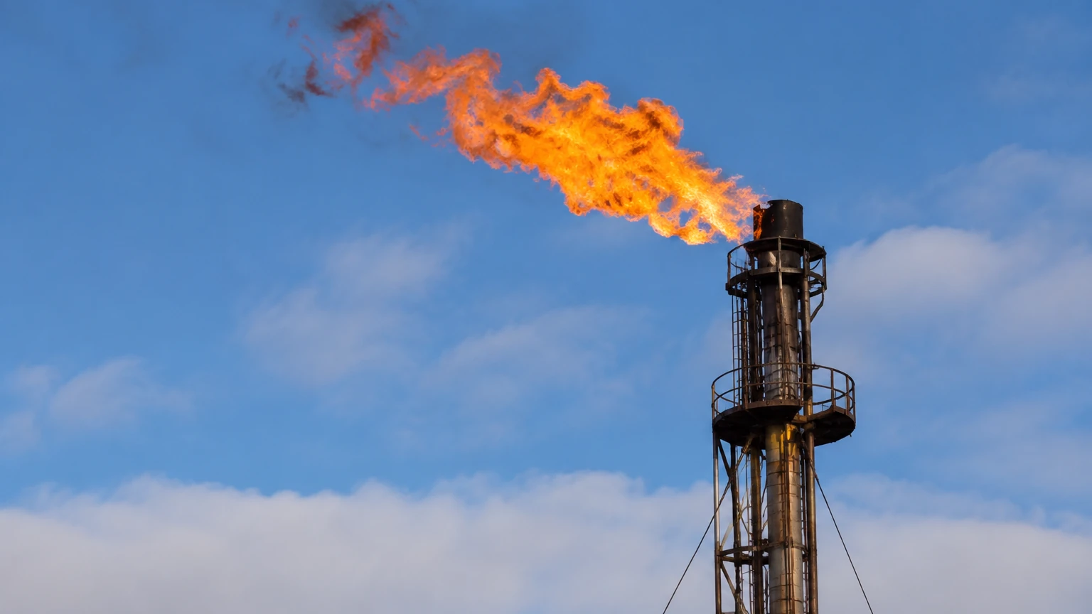
In industrial process environments, particularly within the oil and gas, petrochemical, and chemical sectors, the flare system serves as a critical safety mechanism. A flare gas flow meter is the primary instrument used to quantify the waste gases sent to the flare stack for combustion. Accurate measurement is not merely a matter of operational efficiency; it is a stringent requirement for environmental regulatory compliance, greenhouse gas (GHG) reporting, and loss control.
Measuring flare gas presents unique challenges that distinguish it from standard gas flow applications. The flow rates can vary from near-zero during normal standby operations to extremely high velocities during emergency blowdown events. Furthermore, the composition of flare gas is often inconsistent, containing a mixture of hydrocarbons, hydrogen, nitrogen, and potentially corrosive or dirty components. This guide examines the technical principles, selection criteria, and installation requirements for flare gas flow meters within the broader context of industrial process monitoring.
Core Measurement Principles for Flare Gas
Before selecting a flare gas flow meter, it is essential to understand the physical principles that govern different measurement technologies. Given the extreme turndown ratios required (the ratio between maximum and minimum measurable flow), three main technologies dominate the market.
1. Ultrasonic Transit-Time Technology
Ultrasonic flow meters are widely considered the gold standard for flare gas applications. They operate on the transit-time principle, where two transducers function as both transmitters and receivers. They send ultrasonic pulses diagonally across the pipe, both with and against the gas flow.
* The Principle: The pulse traveling with the flow moves faster than the pulse traveling against it. The difference in time (delta-T) is directly proportional to the gas velocity.
* Advantages: Because the sensors do not obstruct the flow, there is no pressure drop. Modern ultrasonic meters can handle extremely high velocities (up to 100 m/s or 328 fps) and provide a turndown ratio as high as 4000:1. They are also capable of calculating the molecular weight of the gas, which is vital for converting actual volume to mass flow when composition changes.
2. Thermal Mass Flow Measurement
Thermal mass flow meters utilize the heat-conducting properties of the gas to determine mass flow. They typically consist of two sensors: a velocity sensor (heated) and a temperature sensor (reference).
* The Principle: As gas flows past the heated sensor, it carries away heat. The instrument measures the electrical power required to maintain a constant temperature differential between the two sensors. This power is proportional to the mass flow rate.
* Advantages: These meters are highly sensitive to low-flow conditions, making them excellent for detecting small leaks in flare valves. However, they are sensitive to changes in gas composition, as different gases have different thermal conductivities. If the gas composition varies significantly, the accuracy of a thermal mass meter may degrade unless it is equipped with real-time gas analysis integration.
3. Differential Pressure (DP) and Pitot Tubes
While less common for modern flare applications due to limited range, differential pressure meters like Averaging Pitot Tubes are still found in some legacy systems.
* The Principle: These devices create a small pressure drop or sense the impact pressure of the flowing gas. The square root of the pressure difference is proportional to the flow velocity.
* Limitations: The primary drawback is the limited turndown ratio (typically 10:1), which is insufficient for the vast range of flow seen in flare headers. They are also prone to clogging if the gas contains particulates or condensates.
Key Selection Criteria for Industrial Applications
Choosing the right flare gas flow meter requires a comprehensive analysis of the process conditions. Engineers must evaluate the following factors to ensure long-term reliability.
Turndown Ratio and Velocity Range
Flare systems must be monitored during "base flow" (normal leakage) and "emergency relief." A meter must be able to measure velocities as low as 0.03 m/s (0.1 fps) and as high as 100 m/s (328 fps). Ultrasonic meters are generally the only technology that can cover this entire span effectively.
Gas Composition Variability
If the flare gas composition is stable, thermal mass meters offer a cost-effective solution. However, in refineries where the gas might switch from heavy hydrocarbons to high-hydrogen content, ultrasonic meters are preferred because they can use the speed of sound to estimate molecular weight and compensate for density changes.
Pressure and Temperature Extremes
Flare lines often operate at low pressures, sometimes near atmospheric levels. Flow meters must have minimal pressure drop to avoid interfering with the relief valve set points. Additionally, the meter must withstand rapid temperature swings, especially during cryogenic liquid relief or high-temperature steam-out procedures.
Maintenance and Dirty Service
Flare gas is rarely clean. It often contains wax, grit, or corrosive H2S. Selecting a meter with a "no-moving-parts" design is critical. For instance, Welk level measurement instruments, such as those found on the Main Page, emphasize non-contact or robust designs for similar reasons—to minimize maintenance in harsh industrial environments.
Technical Comparison Table
| Feature | Ultrasonic Transit-Time | Thermal Mass | Differential Pressure |
| :— | :— | :— | :— |
| Turndown Ratio | Up to 4000:1 | Up to 1000:1 | 10:1 |
| Accuracy | High (1-2% of reading) | Moderate (2-5%) | Low for flare apps |
| Pressure Drop | Zero | Negligible | Moderate |
| Composition Sensitivity | Low (Compensated) | High | Moderate |
| Maintenance | Low | Low to Moderate | High (Clogging) |
| Typical Velocity | 0.01 to 100 m/s | 0.05 to 60 m/s | 5 to 40 m/s |
Installation and Engineering Considerations
Proper installation is as important as the technology selection itself. Even the most advanced flare gas flow meter will fail to provide accurate data if installed incorrectly.
1. Straight Run Requirements: Most flow technologies require a certain length of straight pipe upstream and downstream to ensure a fully developed flow profile. For ultrasonic meters, this is typically 20 diameters (D) upstream and 10D downstream. If space is limited, flow conditioners may be required, though these can introduce unwanted pressure drops.
2. Nozzle Alignment: For ultrasonic meters, the transducers must be precisely aligned. Any misalignment can cause signal loss, especially at high velocities where "signal drift" occurs due to the gas velocity pushing the sonic pulse away from the receiving transducer.
3. Knock-out Drum Integration: Before gas reaches the flare meter, it passes through a knock-out drum to remove liquids. Reliable level measurement in these drums is essential. Using high-quality level sensors, such as those provided by Welk, ensures that liquids do not carry over into the flare line, which could damage the flow meter or cause "smoking" at the flare tip.
4. Hazardous Area Certification: Given the presence of flammable gases, all electronics must be certified for use in explosive atmospheres (e.g., ATEX, IECEx, or Class I Div 1).
Risks and Regulatory Compliance
Inaccurate flare gas measurement carries significant risks. In many jurisdictions, environmental agencies impose heavy fines for under-reporting flare emissions. Conversely, over-reporting can lead to unnecessary carbon tax expenditures.
* Liquid Entrainment: If liquid droplets are present in the gas stream (multiphase flow), most flow meters will provide erroneous readings. This underscores the importance of effective liquid separation and level monitoring in the upstream knock-out drum.
* Calibration Drift: Over time, sensors may coat or corrode. Regular diagnostic checks, such as signal strength monitoring in ultrasonic meters, are necessary to verify performance without removing the meter from the line.
* Data Integration: The flow meter should be integrated into the plant's Distributed Control System (DCS) or SCADA. This allows for real-time mass balance calculations and immediate alerting during abnormal flaring events.
Frequently Asked Questions (FAQ)
Q: Why can't I use a standard vortex meter for flare gas?
A: Vortex meters rely on the formation of vortices behind a bluff body. At low flow rates (common in standby flare conditions), the gas velocity is too low to generate detectable vortices, leading to a "blind spot" in your measurement.
Q: How does gas composition affect ultrasonic meters?
A: Ultrasonic meters measure the speed of sound. Since the speed of sound varies with the gas's molecular weight and temperature, the meter can use this data to calculate the gas density and provide a more accurate mass flow reading, even if the composition shifts.
Q: What is the impact of high H2S content?
A: High H2S (sour gas) is highly corrosive. In these applications, the wetted parts of the flare gas flow meter (transducers or probes) must be constructed from corrosion-resistant alloys like Hastelloy C276 or Titanium.
Q: Is it necessary to measure temperature and pressure?
A: Yes. To convert actual volumetric flow to standard or normal volumetric flow (and subsequently to mass flow), accurate pressure and temperature compensation is required.
Conclusion
The selection of a flare gas flow meter is a complex engineering decision that impacts safety, environmental compliance, and operational transparency. While ultrasonic transit-time technology offers the most robust performance across the wide range of conditions found in flare headers, thermal mass meters remain a viable option for stable compositions and leak detection.
Successful flare management extends beyond the flow meter itself; it requires a holistic approach to instrumentation. This includes reliable level control in knock-out drums to protect the flare system from liquid carryover. For professionals seeking advanced measurement solutions, exploring the range of radar and ultrasonic instruments on the Welk Main Page can provide the necessary tools for comprehensive process automation and safety. By adhering to strict installation guidelines and choosing technology suited to the specific gas profile, industrial facilities can ensure accurate reporting and safer flaring operations.