Proline Prosonic Flow P 500
Proline Prosonic Flow P 500
In the landscape of industrial process automation, the ability to measure fluid dynamics without compromising the integrity of the piping system is a significant engineering advantage. The Proline Prosonic Flow P 500 represents a sophisticated iteration of ultrasonic clamp-on flow measurement technology. Designed for high-precision applications across various industries—including water management, chemical processing, and oil and gas—this system provides a non-invasive solution for liquid flow monitoring.
While flow measurement is a critical vertical, it often operates in tandem with liquid level monitoring to provide a comprehensive view of process efficiency and inventory. For engineers seeking to integrate these flow data points with reliable tank gauging solutions, reviewing the Main Page of Welk's instrumentation suite offers a broader perspective on how level and flow technologies complement one another in industrial environments.
Measurement Principle: Ultrasonic Transit Time
The Proline Prosonic Flow P 500 operates on the ultrasonic transit-time difference principle. This method relies on the fact that sound waves traveling in the direction of fluid flow move faster than those traveling against it.
How Transit-Time Works
Two ultrasonic sensors are mounted on the exterior of the pipe. These sensors act as both transmitters and receivers. They emit ultrasonic pulses that traverse the pipe wall and the fluid.
1. Downstream Signal: The time it takes for a pulse to travel from the upstream sensor to the downstream sensor ($t_{up \to down}$) is reduced by the velocity of the fluid.
2. Upstream Signal: The time for a pulse to travel from the downstream sensor to the upstream sensor ($t_{down \to up}$) is increased by the fluid velocity.
3. Calculation: The electronics in the P 500 transmitter calculate the time difference ($\Delta t$) between these two paths. This difference is directly proportional to the flow velocity ($v$). By incorporating the known cross-sectional area of the pipe, the system determines the volumetric flow rate.
This principle is highly effective for clean or slightly opaque liquids. Unlike Doppler-shift ultrasonic meters, which require particles or bubbles to reflect signals, transit-time meters like the P 500 are optimized for homogeneous fluids where high accuracy is paramount.
Technical Specifications and Capabilities
The Proline Prosonic Flow P 500 is characterized by its high-performance transmitter and versatile sensor range. It is engineered to handle complex pipe geometries and varying fluid temperatures without requiring process shutdown for installation.
Key Performance Metrics
* Accuracy: Typically ±0.5% of the measured value for most industrial applications, provided the installation follows straight-run requirements.
* Repeatability: ±0.2%.
* Pipe Diameter Range: From DN 15 to DN 4000 (approximately 0.5 inches to 160 inches).
* Temperature Range: Sensors are available to handle fluid temperatures from -40°C to +170°C (-40°F to +338°F).
* Data Integration: Supports industrial protocols including EtherNet/IP, PROFINET, Modbus RS485, and 4-20 mA HART.
The P 500 Transmitter
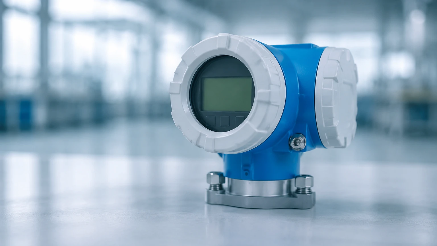
The transmitter serves as the "brain" of the system. It features an integrated web server for remote configuration and advanced diagnostics. This allows maintenance teams to verify the health of the measurement point without specialized software. Furthermore, the P 500 includes "Flow DC" (Discharge Compensation) functionality, which can compensate for flow profile disturbances caused by elbows or transitions when the available straight pipe run is insufficient.
Integration with Level Measurement Systems
In many industrial setups, flow measurement is not an isolated requirement. There is a deep synergy between flow data and level data, particularly in mass balance calculations and leak detection.
Mass Balance and Inventory Control
In a chemical storage facility, a Welk ultrasonic level sensor or radar level meter provides the volume currently held in a tank. The Proline Prosonic Flow P 500 measures the rate at which fluid is being added or removed. By comparing the integrated flow rate over time against the change in level, operators can perform a mass balance check. Discrepancies between the two readings often indicate leaks, sensor drift, or unauthorized withdrawals.
Pump Protection and Efficiency
Level sensors are frequently used to prevent pumps from running dry. However, combining level data with flow data from a clamp-on meter allows for more nuanced control. For instance, if the level in a supply tank is sufficient but the flow rate measured by the P 500 is lower than expected, it may indicate a partial blockage or a pump cavitation issue before the level reaches a critical low-point alarm.
Selection Criteria for Ultrasonic Flowmeters
Choosing the correct configuration for the Proline Prosonic Flow P 500 requires a detailed analysis of the application environment. The following table outlines the primary factors to consider:
| Factor | Requirement | Impact on Measurement |
| :— | :— | :— |
| Pipe Material | Carbon steel, stainless steel, plastic, or ductile iron. | Sound velocity varies by material; the meter must be programmed with the correct pipe properties. |
| Fluid Type | Water, chemicals, oils, or solvents. | The fluid must be sonically conductive and have less than 5% solids or gas bubbles by volume. |
| Pipe Lining | Cement, bitumen, or epoxy. | Linings must be well-bonded to the pipe wall to prevent signal attenuation at the interface. |
| Straight Pipe Run | Ideally 15 diameters upstream and 5 diameters downstream. | Insufficient straight runs lead to turbulent flow profiles, reducing accuracy. |
| Temperature | Fluid and ambient temperature. | High temperatures require specialized coupling pads or high-temp sensor variants. |
Installation Considerations
The primary advantage of the Proline Prosonic Flow P 500 is its clamp-on design, which eliminates the need for cutting pipes or welding flanges. However, the quality of the installation directly dictates the accuracy of the data.
Sensor Positioning
Sensors should ideally be installed on horizontal pipe sections. If installed on vertical pipes, the flow must be in an upward direction to ensure the pipe remains completely full. To avoid interference from sediment at the bottom of the pipe or air pockets at the top, sensors are typically mounted at the 3 o'clock and 9 o'clock positions (the "sides" of the pipe).
Surface Preparation
The exterior of the pipe must be cleaned of loose scale, rust, and thick paint. A coupling agent (typically a silicone-based grease or a permanent adhesive pad) is applied between the sensor face and the pipe wall. This agent eliminates air gaps, which would otherwise reflect the ultrasonic signals and prevent them from entering the fluid.
Mounting Modes
Depending on the pipe diameter and fluid properties, the sensors can be mounted in different configurations:
* V-Mode: The signal reflects off the opposite pipe wall once. This is common for medium-sized pipes.
* Z-Mode: Sensors are placed on opposite sides of the pipe, and the signal travels directly across. This is used for large pipes or highly attenuating fluids.
* W-Mode: The signal reflects multiple times, increasing the path length for better resolution in very small pipes.
Limitations and Challenges
While the Proline Prosonic Flow P 500 is a versatile tool, engineers must be aware of its physical limitations:
1. Entrained Air and Solids: High concentrations of bubbles or suspended solids (typically >5%) scatter the ultrasonic signal, leading to a loss of signal (Signal-to-Noise ratio degradation).
2. Pipe Condition: If the interior of the pipe is heavily scaled or corroded, the path of the ultrasonic pulse can become unpredictable. In such cases, cleaning the pipe or using an inline meter may be necessary.
3. Laminar vs. Turbulent Flow: The meter calculates flow based on a profile factor. At low velocities (Reynolds numbers in the transition zone), the flow profile is less predictable, which can slightly increase the margin of error.
Maintenance and Troubleshooting
Because the sensors do not come into contact with the process fluid, they are not subject to wear, corrosion, or clogging. This makes the P 500 a low-maintenance device compared to mechanical meters or electromagnetic flowmeters in corrosive environments.
* Signal Strength Monitoring: The transmitter provides a signal strength indicator. A gradual decline in signal strength often suggests that the coupling grease has dried out or that the pipe's internal scaling has increased.
* Heartbeat Technology: The system includes self-diagnostic features that continuously monitor the health of the electronics and the sensor integrity. This allows for "verification without interruption," where the device generates a report confirming it is still within its original calibration specifications.
* Zero-Point Adjustment: In critical applications, a zero-point adjustment should be performed during commissioning under "no-flow" conditions (with the pipe full and valves closed) to eliminate any residual offset.
Frequently Asked Questions (FAQ)
Q: Can the Prosonic Flow P 500 measure gas flow?
A: No, the P 500 is specifically designed for liquid applications. Gas flow measurement requires different ultrasonic frequencies and sensor configurations due to the significantly lower density and different sound velocity of gases.
Q: Does the pipe need to be empty during installation?
A: No. One of the main benefits of this clamp-on system is that it can be installed while the process is running. However, for the initial calibration and zero-point adjustment, it is best if the flow can be temporarily stopped while the pipe remains full.
Q: How does the P 500 handle different pipe thicknesses?
A: During setup, the user enters the pipe material, outer diameter, and wall thickness into the transmitter. The P 500 then calculates the exact distance required between the two sensors to ensure the ultrasonic pulse is correctly received after reflecting or traversing the pipe.
Q: Is it compatible with Welk level monitoring systems?
A: Yes. Since the P 500 outputs standard industrial signals (like 4-20mA or Modbus), its data can be integrated into the same PLC or SCADA system that monitors Welk's level instruments, allowing for a unified process control strategy.
For more information on selecting the right instrumentation for your specific industrial application, including detailed guidance on radar and ultrasonic level sensors, please visit the Main Page.