Pressure Trasducer
Pressure Trasducer
In the landscape of industrial automation and process control, the accurate measurement of liquid levels is a fundamental requirement. Among the various technologies available, the use of a pressure trasducer—often referred to as a pressure transmitter in high-precision contexts—remains one of the most reliable and cost-effective methods for determining the volume or height of a liquid within a vessel. By converting the physical force of a fluid into an electrical signal, these instruments allow for real-time monitoring and control in sectors ranging from wastewater treatment to chemical processing.
Understanding the technical nuances of a pressure trasducer is essential for engineers and procurement specialists. This guide explores the underlying physics, various types of sensors, selection criteria, and practical installation strategies to ensure long-term operational success. For a comprehensive overview of available technologies, engineers can visit the Main Page to review product options and application support.
Principles of Hydrostatic Level Measurement
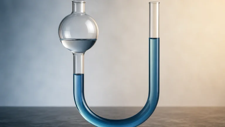
The primary method by which a pressure trasducer measures level is through hydrostatic pressure. This principle is based on the fact that the pressure at a specific point within a static liquid is directly proportional to the height of the liquid column above that point.
The Hydrostatic Equation
The relationship is defined by the formula:
P = ρ × g × h
Where:
* P is the hydrostatic pressure (measured in Pascals or bar).
* ρ (rho) is the density of the liquid (kg/m³).
* g is the acceleration due to gravity (approximately 9.81 m/s²).
* h is the height of the liquid column (meters).
Because gravity is constant and the density of many liquids (like water) remains relatively stable under consistent temperatures, the pressure measured by the sensor can be directly translated into a linear level reading. For example, in a tank of water with a density of 1000 kg/m³, a pressure reading of 0.1 bar (10 kPa) corresponds to a liquid height of approximately 1.02 meters.
Sensing Technologies
Most modern pressure trasducers utilize one of two primary sensing technologies:
1. Piezoresistive Sensors: These use a silicon diaphragm with integrated strain gauges. When pressure is applied, the diaphragm deforms, changing the electrical resistance. These are highly sensitive and widely used for clean water applications.
2. Ceramic Capacitive Sensors: These feature a ceramic diaphragm that acts as one plate of a capacitor. Pressure changes the distance between the plates, altering the capacitance. Ceramic sensors are exceptionally robust and resistant to corrosion and mechanical wear, making them ideal for aggressive chemicals or abrasive slurries.
Types of Pressure Transducers for Level Applications
Selecting the right pressure trasducer depends heavily on the tank geometry and the nature of the medium being measured. There are two primary configurations used in level measurement.
Submersible Level Transmitters
Submersible sensors are designed to be lowered directly into the liquid. They are housed in a waterproof casing (usually 316L stainless steel or plastic like PVC or PVDF) and connected by a specialized cable. This cable contains a small vent tube that allows the sensor to compensate for changes in atmospheric pressure, ensuring that the measurement only reflects the liquid's weight.
Externally Mounted (Threaded or Flanged)
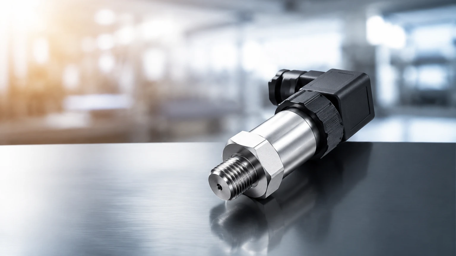
For tanks where an internal probe is not feasible, an externally mounted pressure trasducer is installed at the bottom or side of the vessel. These units connect via a threaded process connection (e.g., G1/2 or NPT) or a flange. In closed, pressurized tanks, a differential pressure (DP) transmitter is used, measuring the difference between the bottom pressure and the top gas-space pressure to negate the effect of the tank's internal pressure.
Technical Selection Criteria
When specifying a pressure trasducer for an industrial project, several technical parameters must be confirmed to ensure accuracy and longevity.
Pressure Range and Overload
The sensor's range should be closely matched to the maximum expected liquid height. Selecting a range that is too high will reduce the resolution and accuracy of the reading. Furthermore, the "overload pressure" or "burst pressure" rating must be considered to protect the sensor against sudden pressure spikes or surges within the system.
Material Compatibility
The wetted parts—the components of the pressure trasducer that come into contact with the fluid—must be chemically compatible.
* 316L Stainless Steel: Standard for water and mild oils.
* Tantalum or Hastelloy: Required for highly corrosive acids.
* Ceramic Diaphragms: Preferred for fluids containing solids that might abrade a metal diaphragm.
Output Signals and Communication
In B2B industrial environments, the standard output is a 4-20mA analog signal, which is highly resistant to electrical noise over long distances. However, many modern systems require digital communication protocols such as RS485 (Modbus RTU) or HART, which allow for remote calibration and diagnostic feedback.
Comparison Table: Level Measurement Technologies
| Feature | Submersible Pressure Sensor | External Pressure Transmitter | Differential Pressure (DP) |
| :— | :— | :— | :— |
| Best Use Case | Deep wells, open reservoirs, sumps | Process tanks, small vessels | Pressurized tanks, boilers |
| Installation | Suspended by cable | Side-wall mounting | Dual-port connection |
| Maintenance | Easy to pull out | Requires tank draining or isolation valve | Complex piping/manifolds |
| Cost | Low to Moderate | Moderate | High |
| Atmospheric Comp. | Integrated vent tube | Atmospheric vent | High/Low side ports |
Installation Considerations and Best Practices
Proper installation is critical to the performance of a pressure trasducer. Even the most accurate sensor will provide poor data if environmental factors are not addressed.
Avoiding Turbulence and Flow
In tanks with agitators or high-velocity inlet flows, a pressure trasducer should be installed inside a "stilling well" or a perforated pipe. This protects the diaphragm from the kinetic energy of the moving fluid, which can cause erratic readings or mechanical damage.
Cable Management and Venting
For submersible units, the cable must be securely anchored to prevent the sensor from moving. The vent tube within the cable must remain unobstructed. It is recommended to use a desiccant box at the termination point to prevent moisture from entering the vent tube, which could lead to internal condensation and sensor failure.
Temperature Effects
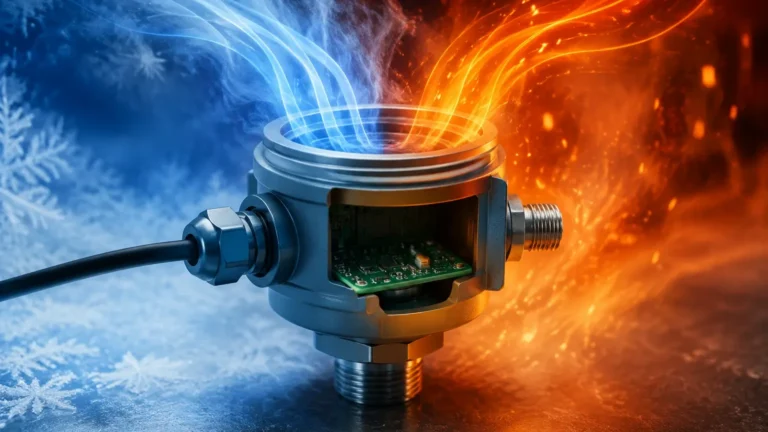
Liquid density changes with temperature. If a process undergoes significant temperature fluctuations, the pressure trasducer's output may drift even if the actual level remains constant. Advanced transmitters include integrated temperature compensation, but in high-precision applications, a separate temperature sensor may be required to calculate the corrected density in the control system.
Limitations and Common Risks
While hydrostatic pressure measurement is versatile, it is not without limitations.
1. Density Sensitivity: Since the sensor measures weight, any change in the liquid's specific gravity (due to concentration changes or temperature) will result in a level error.
2. Clogging and Coating: In applications involving wastewater or viscous syrups, the sensing diaphragm can become coated or clogged. Using a "flush diaphragm" design, where the sensing surface is level with the process connection, can mitigate this risk.
3. Mechanical Shock: Dropping a submersible pressure trasducer or hitting the diaphragm during installation can permanently shift the zero point or destroy the sensing element.
Frequently Asked Questions (FAQ)
Q: Can a pressure trasducer be used in a pressurized tank?
A: A standard hydrostatic sensor cannot distinguish between liquid pressure and gas head pressure. In pressurized vessels, a differential pressure transmitter must be used to subtract the head pressure from the total bottom pressure.
Q: How often should a pressure trasducer be calibrated?
A: For most industrial applications, an annual calibration check is sufficient. However, in regulated industries like food and beverage or pharmaceuticals, semi-annual calibration may be required to ensure compliance with safety standards.
Q: What is the maximum depth a submersible sensor can measure?
A: Standard industrial units can measure depths up to 200 meters (20 bar), though specialized deep-well sensors are available for even greater depths. The limiting factor is often the strength and weight of the suspension cable.
Q: Does the shape of the tank affect the reading?
A: No. Hydrostatic pressure depends only on the vertical height of the liquid, not the volume or shape of the container. However, if you need to calculate volume from the level reading, the tank geometry must be programmed into your PLC or display unit.
Conclusion
The pressure trasducer remains a cornerstone of industrial level measurement due to its simplicity and reliability. By understanding the relationship between pressure and depth, and by carefully selecting materials and installation methods, engineers can implement robust monitoring solutions for almost any liquid medium. Whether managing a simple water tank or a complex chemical reactor, choosing the right sensor technology is the first step toward process optimization. For detailed product specifications and engineering support, please refer to the Main Page to explore the full range of industrial measurement solutions.