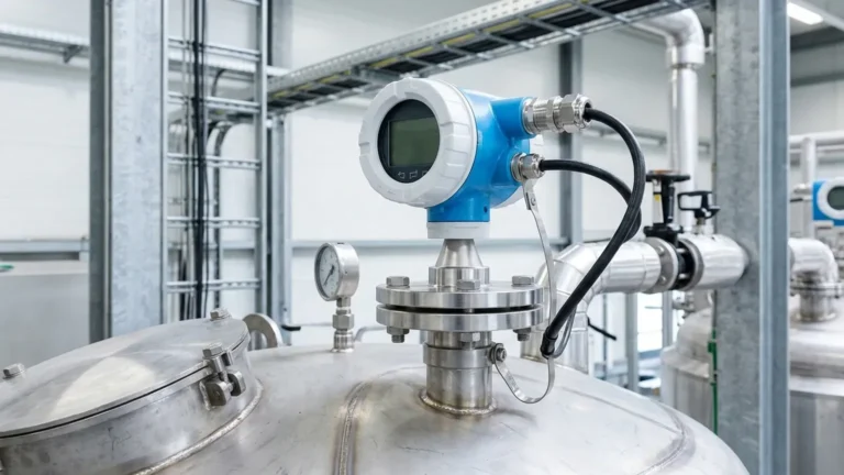
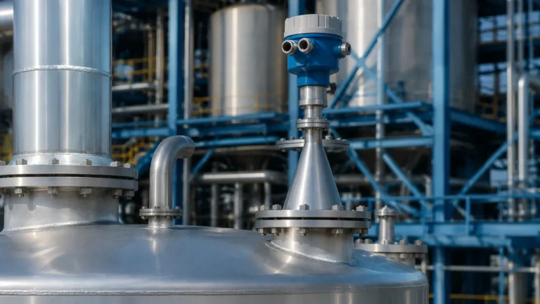
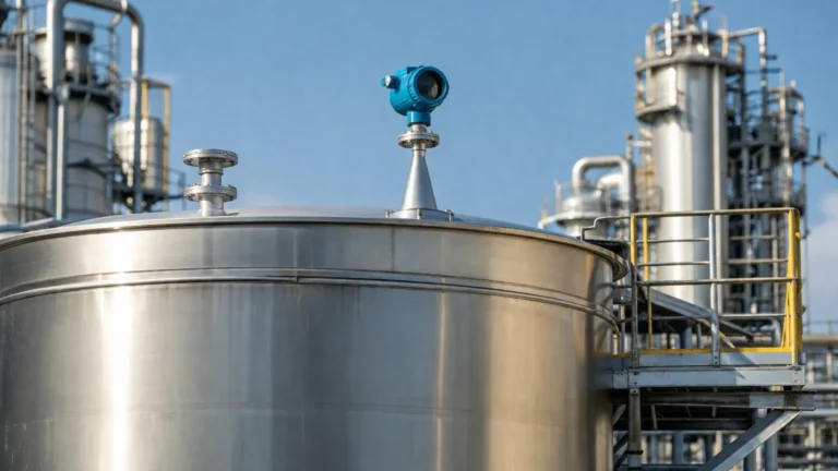
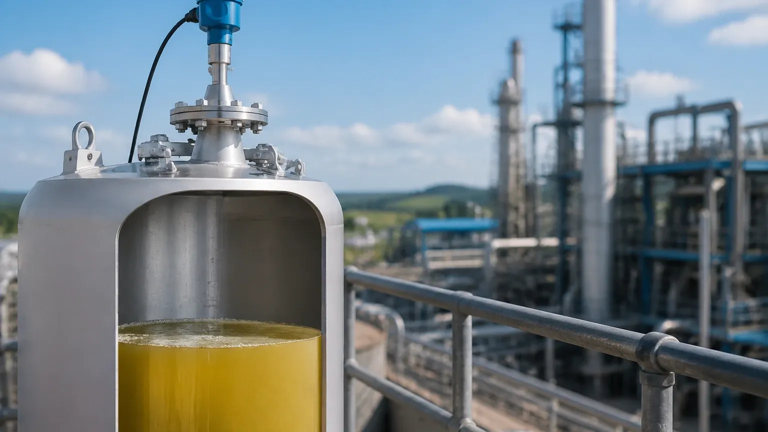
Tank Radar Level Transmitter
Tank Radar Level Transmitter: A Comprehensive Engineering Guide to Selection and Application
In the landscape of industrial process automation, the accurate measurement of liquid and solid levels within storage and process vessels is critical for operational safety, inventory management, and process efficiency. Among the various technologies available, the tank radar level transmitter has emerged as a premier solution due to its non-contact nature and high reliability in challenging environments.
Modern Radar Level Meters utilize advanced electromagnetic wave technology to provide continuous level monitoring. Unlike contact-based methods such as floats or displacers, radar technology is largely unaffected by changes in process temperature, pressure, or the density of the medium being measured. This article provides a detailed technical overview of radar measurement principles, selection criteria, and practical installation guidelines for industrial engineers and procurement specialists.
1. Understanding Radar Measurement Principles
Before selecting a tank radar level transmitter, it is essential to understand the two primary methods used to calculate distance: Pulse Radar and Frequency Modulated Continuous Wave (FMCW).
1.1 Pulse Radar (Time of Flight)
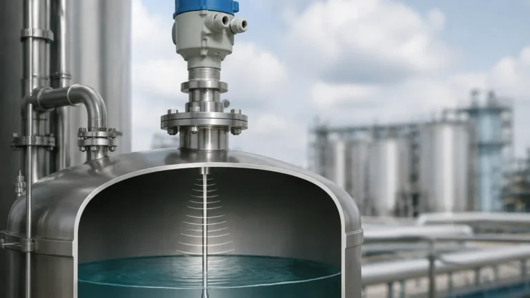
Pulse radar transmitters emit high-frequency microwave pulses toward the surface of the medium. These pulses travel at the speed of light. When they hit the surface of the product, a portion of the energy is reflected back to the antenna. The instrument measures the "Time of Flight" (ToF)—the time elapsed between the emission of the pulse and the reception of the echo.
The distance ($D$) is calculated using the formula:
$D = (c \times t) / 2$
Where $c$ is the speed of light and $t$ is the measured time. Since the distance from the sensor to the tank bottom ($L$) is known, the level ($H$) is simply $L – D$.
1.2 Frequency Modulated Continuous Wave (FMCW)
FMCW radar does not send pulses; instead, it transmits a continuous signal with a frequency that changes linearly over time (a frequency sweep). The signal reflects off the material surface and is received by the antenna. By the time the reflection returns, the transmitter is emitting a different frequency. The difference between the transmitted frequency and the received frequency is directly proportional to the distance. FMCW is generally more accurate and provides a better signal-to-noise ratio, making it ideal for high-precision applications or environments with significant vapor or dust.
2. Key Selection Criteria for Industrial Tanks
Choosing the right tank radar level transmitter requires a thorough analysis of the application environment. The following factors are decisive in equipment selection.
2.1 Frequency Range (6GHz, 26GHz, and 80GHz)
The frequency of the radar signal determines the beam angle and the instrument’s ability to handle obstacles or surface agitation.
* 6GHz (C-Band): Known for its ability to penetrate heavy foam and steam. However, it has a wide beam angle, requiring large nozzles and clear paths free of internal tank obstructions.
* 26GHz (K-Band): The traditional "workhorse" of the industry. It offers a balance between a manageable beam angle and reliable performance in most liquid storage tanks.
* 80GHz (W-Band): The current state-of-the-art. 80GHz radar features a very narrow beam angle (often as small as 3°), allowing for installation in narrow tanks, near walls, or in vessels with internal agitators and heating coils. It also offers superior resolution for measuring solids and powders.
2.2 Dielectric Constant ($ε_r$)
The dielectric constant of the medium determines how much energy is reflected back to the sensor.
* High Dielectric Materials: Water-based liquids ($ε_r > 10$) reflect signals very well, making them easy to measure.
* Low Dielectric Materials: Hydrocarbons, oils, and certain solvents ($ε_r < 2$) reflect very little energy. For these applications, a high-sensitivity tank radar level transmitter or a Guided Wave Radar (GWR) may be required.
2.3 Process Conditions
Engineers must confirm the maximum operating temperature and pressure. High-temperature applications (up to 400°C / 752°F) often require specialized antenna cooling or ceramic seals. Similarly, high-pressure vessels require robust flange connections and pressure-rated housing.
3. Practical Selection Table
The following table summarizes typical configurations for various industrial scenarios:
| Application Type | Recommended Frequency | Antenna Type | Typical Accuracy |
| :— | :— | :— | :— |
| Large Water Storage | 26 GHz | Horn / Plastic Encapsulated | ±3 mm (0.12 in) |
| Chemical Buffer Tank | 80 GHz | PTFE Lens Antenna | ±1 mm (0.04 in) |
| Heavy Dust Silos (Solids) | 80 GHz | Flange with Aiming Kit | ±5 mm (0.20 in) |
| Corrosive Acid Tanks | 26 GHz / 80 GHz | All-PTFE Sealed Antenna | ±2 mm (0.08 in) |
| High-Pressure Oil Storage | 26 GHz | Stainless Steel Horn | ±3 mm (0.12 in) |
4. Installation Considerations and Constraints
Even the most advanced tank radar level transmitter will fail to provide accurate data if installed incorrectly. Engineers should adhere to the following guidelines:
4.1 Mounting Position
* Avoid the Center: Do not mount the transmitter in the exact center of a circular tank. This can lead to multiple reflections (parabolic effect) that interfere with the primary echo.
* The 1/6th Rule: A common rule of thumb is to mount the sensor at a distance of 1/6th of the tank diameter from the tank wall. This minimizes wall interference while avoiding the center.
* Nozzle Height: The antenna should ideally extend slightly beyond the mounting nozzle to prevent the nozzle edge from creating a "ringing" effect or false echoes.
4.2 Obstruction Management
Internal structures like ladders, pipes, and agitators can create false reflections. While modern software allows for "False Echo Suppression" (mapping out static reflections), it is best to provide a clear "line of sight" to the product surface. If an agitator is present, the radar should be positioned where the beam does not hit the blades directly, or an 80GHz unit with a narrow beam should be used.
4.3 Beam Angle and Dead Zones
The "Dead Zone" or blocking distance is the area immediately below the antenna where measurement is not possible. For liquid tanks, this is typically 100mm to 300mm (4 to 12 inches). Ensure the tank is never overfilled into this zone to prevent signal loss.
5. Limitations and Application Risks
While highly versatile, radar technology has specific limitations that must be addressed during the design phase:
1. Heavy Foam: While low-frequency radar can penetrate some foam, thick, dense foam (like firefighting foam or certain chemical surfactants) can absorb the radar signal entirely, leading to a "Loss of Echo" (LOE) error.
2. Turbulent Surfaces: Rapidly boiling or heavily agitated liquids can scatter the radar signal. In these cases, using a stilling well (a bypass pipe) can provide a calm surface for the radar to measure.
3. Vacuum Conditions: While radar works in a vacuum, the sealing materials of the transmitter must be rated for vacuum service to prevent air ingress or equipment damage.
4. Condensation and Buildup: In high-humidity applications, droplets can form on the antenna. Choosing a lens antenna with a convex shape or a PTFE coating helps moisture shed off, maintaining signal integrity.
6. Frequently Asked Questions (FAQs)
Q: Does the gas composition in the tank affect radar accuracy?
A: Generally, no. Unlike ultrasonic sensors, which depend on the speed of sound (which varies with gas density), radar uses electromagnetic waves. Only extreme pressures or specific high-dielectric gases at high concentrations significantly affect the speed of light, but for 99% of industrial applications, this is negligible.
Q: How often does a tank radar level transmitter need calibration?
A: Radar transmitters are solid-state devices with no moving parts. Once commissioned and mapped to the tank geometry, they typically do not drift. Annual verification is recommended for ISO compliance, but full recalibration is rarely necessary.
Q: Can radar measure through a plastic tank roof?
A: Yes. If the tank is made of a non-conductive material like polyethylene or fiberglass (GRP) and is not reinforced with metal mesh, the radar signal can pass through the roof. This allows for "non-invasive" measurement where the sensor is mounted outside the tank.
7. Conclusion
The selection of a tank radar level transmitter is a balance between process requirements, tank geometry, and budget. For most modern industrial applications, the 80GHz frequency offers the greatest flexibility and ease of installation due to its narrow beam and high precision. However, for specific chemical processes involving heavy foam or extreme steam, lower frequency options remain relevant.
When sourcing Radar Level Meters, it is vital to provide the manufacturer with the medium's dielectric constant, the tank's internal dimensions, and the presence of any obstructions. Proper planning during the specification phase ensures a maintenance-free measurement solution that enhances the safety and productivity of the entire facility.