Ultrasonic Flow Meter for Water
Ultrasonic Flow Meter for Water
In modern industrial water management, the ability to measure flow rates accurately without interrupting process flow or compromising the integrity of piping systems is a critical requirement. The ultrasonic flow meter for water has emerged as a primary solution for these needs, offering a blend of precision, reliability, and non-invasive installation. As global industries move toward more automated and data-driven water treatment and distribution systems, understanding the technical nuances of ultrasonic technology is essential for engineers and plant managers.
This guide provides a comprehensive technical overview of ultrasonic flow measurement principles, selection criteria, and installation best practices, specifically tailored for B2B applications in water treatment, chemical processing, and industrial automation.
Measurement Principles: How Ultrasonic Technology Works
Ultrasonic flow meters operate by utilizing acoustic waves to determine the velocity of a fluid. Unlike mechanical flow meters that rely on moving parts like turbines or paddles, ultrasonic meters use transducers to send and receive sound pulses through the water. There are two primary methods used in these instruments: Transit Time and Doppler Effect.
Transit Time Difference Method
The transit time method is the most common technique used for an ultrasonic flow meter for water, particularly when the water is clean or contains very low concentrations of suspended solids or air bubbles.
This method employs two transducers, typically labeled as Upstream (A) and Downstream (B). Both transducers function as both transmitters and receivers. A sound pulse is sent from Transducer A to Transducer B, and then from B to A. Because the water is moving, the sound pulse traveling in the direction of the flow (downstream) moves faster than the pulse traveling against the flow (upstream).
The time difference ($Δt$) between these two signals is directly proportional to the velocity of the water. The governing equation for flow velocity ($v$) in a transit time system is:
$$v = K · Δt / T_{avg}^2$$
Where $K$ is a calibration constant and $T_{avg}$ is the average transit time. Once the velocity is determined, the volumetric flow rate is calculated by multiplying the velocity by the cross-sectional area of the pipe.
Doppler Effect Method
The Doppler method is utilized when the water contains significant amounts of acoustic reflectors, such as suspended solids, grit, or entrained air bubbles. In this principle, a transducer emits an ultrasonic signal into the water at a known frequency. This signal reflects off the moving particles or bubbles and returns to a receiver.
According to the Doppler effect, the frequency of the reflected signal shifts based on the velocity of the particles. By measuring this frequency shift, the meter calculates the flow velocity. While highly effective for wastewater or slurries, the Doppler method is generally less accurate than transit time for clean water applications because it measures the velocity of the particles rather than the fluid itself.
Types of Ultrasonic Flow Meters for Water
When selecting an ultrasonic flow meter for water, engineers must choose between two primary physical configurations: clamp-on and inline (wetted).
Clamp-On Ultrasonic Flow Meters
Clamp-on meters are the hallmark of non-invasive flow measurement. The transducers are mounted to the outside of the pipe using tracks or chains and a coupling agent (such as silicone grease or ultrasonic gel) to ensure the signal passes through the pipe wall.
* Advantages: No process downtime for installation, zero pressure drop, no risk of leakage, and no contact with corrosive or high-pressure fluids.
* Ideal Applications: Retrofitting existing systems, temporary flow surveys, and large-diameter pipes where cutting the line would be cost-prohibitive.
Inline (Wetted) Ultrasonic Flow Meters
Inline meters involve a factory-calibrated flow tube that is installed directly into the piping system via flanges or threads. The transducers are either in direct contact with the water or protected by a thin window within the pipe wall.
* Advantages: Higher accuracy (often up to ±0.5%), better performance in low-flow conditions, and independence from pipe material inconsistencies.
* Ideal Applications: Custody transfer, high-precision chemical dosing, and new plant constructions where long-term stability is paramount.
Practical Selection Criteria
Choosing the right ultrasonic flow meter for water requires a detailed analysis of the application's physical and chemical parameters. The following table provides a comparison of key selection factors:
| Criteria | Transit Time (Clean Water) | Doppler (Dirty Water) |
| :— | :— | :— |
| Fluid Clarity | < 2% solids/bubbles | > 100 ppm of 100μm particles |
| Typical Accuracy | ±0.5% to ±2% of rate | ±2% to ±5% of full scale |
| Pipe Size Range | 15 mm to 6000 mm | 25 mm to 5000 mm |
| Velocity Range | 0.01 m/s to 12 m/s | 0.1 m/s to 10 m/s |
| Maintenance | Low (no moving parts) | Low (no moving parts) |
| Installation Cost | Low (Clamp-on) | Low (Clamp-on) |
Key Considerations for Engineers:
1. Pipe Material and Condition: For clamp-on meters, the sound must travel through the pipe wall. Materials like carbon steel, stainless steel, and PVC are excellent conductors. However, pipes with thick internal liners (like cement or bitumen) or significant internal corrosion/scaling can attenuate the signal, leading to measurement failure.
2. Fluid Temperature: The speed of sound in water changes with temperature (approximately 1480 m/s at 20°C). Advanced meters include temperature compensation to adjust the calculation automatically.
3. Required Accuracy: If the application involves billing or high-value chemical mixing, an inline transit-time meter is usually required. For general process monitoring, a clamp-on model is often sufficient.
Installation Guidelines and Straight Pipe Requirements
The accuracy of any ultrasonic flow meter for water is heavily dependent on the flow profile within the pipe. For the meter to provide a stable reading, the flow should be laminar and fully developed.
Straight Run Requirements
To avoid turbulence caused by valves, pumps, or elbows, specific straight pipe runs are required upstream and downstream of the sensor location. Standard engineering practice suggests:
* Upstream: Minimum of 10 diameters (10D) of straight pipe.
* Downstream: Minimum of 5 diameters (5D) of straight pipe.
If the meter is installed after a pump or a partially open valve, the upstream requirement may increase to 20D or 30D to allow the turbulence to subside.
Transducer Mounting Positions
For horizontal pipes, transducers should never be mounted at the very top or very bottom of the pipe. The top of the pipe often collects air bubbles, while the bottom may accumulate sediment. Both conditions will block or distort the ultrasonic signal. The ideal mounting position is at the "3 o'clock" and "9 o'clock" positions (the horizontal plane).
For vertical pipes, the flow should always be upward. This ensures the pipe remains completely full of water, which is a prerequisite for accurate ultrasonic measurement.
Limitations and Common Challenges
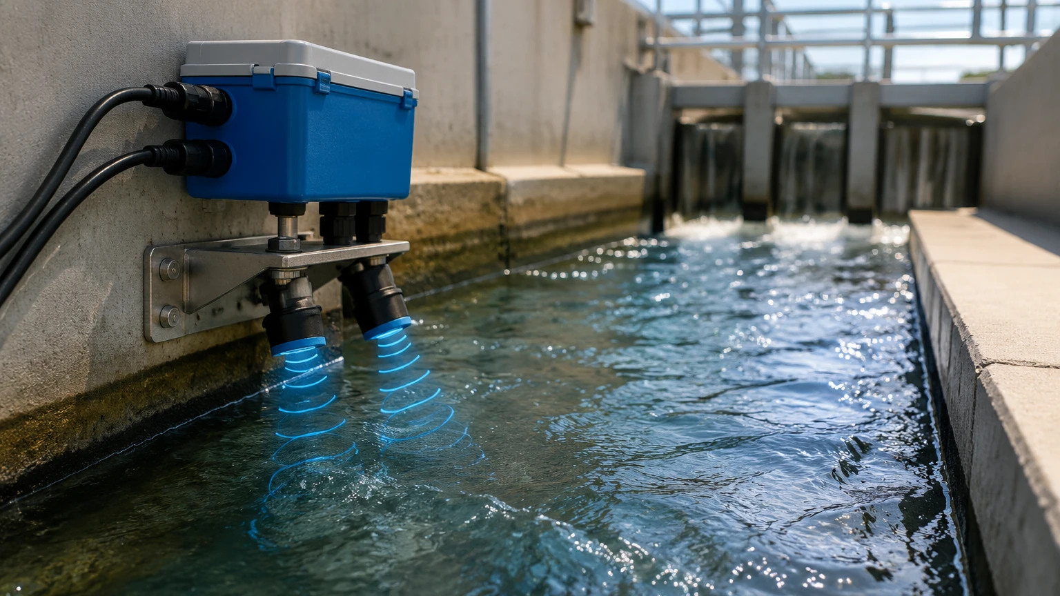
While highly versatile, an ultrasonic flow meter for water is not a universal solution. Engineers must be aware of the following limitations:
1. Full Pipe Requirement: Ultrasonic meters cannot measure flow in partially full pipes (unless specifically designed for open-channel flow using level-to-flow conversion). If air pockets exist, the signal will be lost.
2. Signal Attenuation: High concentrations of suspended solids or bubbles can scatter the signal in transit-time meters. Conversely, extremely pure deionized water may lack the particles needed for Doppler meters to function.
3. Pipe Wall Interference: Thick-walled pipes or pipes with significant exterior coatings (like heavy insulation or thick paint) must be prepared properly. Paint should be sanded down to the bare metal at the transducer contact points.
4. Acoustic Short-Circuiting: In some metallic pipes, the sound signal may travel through the pipe wall faster than through the water, creating "noise" that the meter must be able to filter out via advanced signal processing.
Integration with Level Measurement Systems
In many industrial water applications, flow measurement is only one part of the equation. Companies like Welk provide a range of instruments that work in tandem with flow meters to provide a complete picture of fluid dynamics. For instance, in wastewater treatment, an ultrasonic flow meter for water might be used on the pressurized discharge line, while a radar or ultrasonic level sensor is used to monitor the intake wet well or chemical storage tanks.
Integrating flow data with level data allows for advanced diagnostics, such as identifying pump efficiency losses or detecting leaks in closed-loop systems. For more information on comprehensive measurement solutions, you can visit the Main Page to explore how different sensor technologies can be combined for optimized process control.
Frequently Asked Questions (FAQ)
Q: Can an ultrasonic flow meter measure water in both directions?
A: Yes, most transit-time ultrasonic meters are inherently bi-directional. They can measure flow in both directions and provide a net flow totalization.
Q: How often does a clamp-on flow meter need to be recalibrated?
A: Since there are no moving parts to wear out, the electronic calibration of the meter is very stable. However, the coupling agent between the transducer and the pipe can dry out over several years. It is recommended to check the signal strength annually and re-apply coupling grease if necessary.
Q: What is the minimum flow velocity an ultrasonic meter can detect?
A: High-quality ultrasonic meters can detect velocities as low as 0.01 m/s (0.03 ft/s), making them much more sensitive than traditional mechanical meters at low flow rates.
Q: Does the pressure of the water affect the flow reading?
A: No, the speed of sound in water is not significantly affected by pressure changes within standard industrial ranges. However, the pipe must remain full, so a minimum backpressure is often required to prevent cavitation or air gaps.
Conclusion
The ultrasonic flow meter for water represents a sophisticated, reliable, and cost-effective choice for modern industrial applications. By understanding the differences between transit-time and Doppler principles, adhering to strict installation guidelines regarding straight pipe runs, and selecting the appropriate mounting style (clamp-on vs. inline), engineers can ensure long-term accuracy and minimal maintenance. Whether used for simple water distribution or complex chemical processing, these instruments provide the data necessary for efficient and sustainable water management. For technical support and product selection across various level and flow measurement technologies, refer to the resources available on the Main Page.