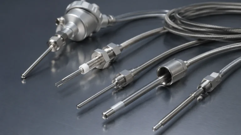
Waters Conductivity Detector
Waters Conductivity Detector
In the landscape of industrial process control, the measurement of liquid properties is as critical as the measurement of volume or level. A waters conductivity detector serves as a primary instrument for assessing the ionic concentration of aqueous solutions, providing essential data for water treatment, chemical processing, and power generation. While often associated with analytical chemistry, conductivity detection is a fundamental component of industrial automation, particularly when used in conjunction with level measurement systems to ensure process safety and product consistency.
Conductivity is a measure of a solution's ability to conduct an electrical current, which is directly proportional to the concentration of dissolved ions. In industrial environments, monitoring the conductivity of various process waters—ranging from ultrapure water in semiconductor fabrication to high-salinity wastewater—requires robust instrumentation capable of withstanding harsh conditions while maintaining high accuracy.
Fundamental Measurement Principles
To effectively implement a waters conductivity detector, engineers must understand the underlying physics of electrolytic conduction. Unlike metallic conduction, where electrons carry the charge, in liquids, the charge is transported by cations and anions.
Ohm’s Law in Liquids
The basic principle relies on Ohm’s Law ($V = I \times R$). A conductivity sensor applies an alternating current (AC) voltage to electrodes immersed in the liquid and measures the resulting current. The conductance ($G$) is the reciprocal of resistance ($R$) and is measured in Siemens (S). However, to make this measurement independent of the sensor's physical dimensions, it is converted to conductivity ($σ$), measured in Siemens per meter (S/m) or microsiemens per centimeter (µS/cm).
The Cell Constant (K)
The geometry of the sensor electrodes is defined by the cell constant ($K$), which is the ratio of the distance between electrodes ($L$) to the cross-sectional area of the liquid between them ($A$):
$$K = L / A$$
* Low Cell Constants (e.g., K=0.1): Used for low-conductivity liquids like deionized water, where the electrodes are placed close together to capture a measurable signal.
* High Cell Constants (e.g., K=10): Used for high-conductivity liquids like seawater or concentrated acids, where the electrodes are spaced further apart to prevent current saturation.
Temperature Compensation
Conductivity is highly temperature-dependent; typically, the conductivity of an aqueous solution increases by 1% to 3% per degree Celsius. Most modern detectors incorporate a Resistance Temperature Detector (RTD), such as a PT100 or PT1000, to provide automatic temperature compensation, normalizing the reading to a reference temperature (usually 25°C).
Conductivity in Level Measurement Applications
In the context of industrial level control, conductivity is frequently utilized for point-level detection. Conductive level switches are among the most reliable and cost-effective solutions for detecting the presence of water-based liquids in tanks and vessels. For a broader overview of how these technologies integrate into plant-wide systems, engineers often consult the Main Page of instrumentation providers to compare conductive probes with technologies like radar or ultrasonic sensors.
How Conductive Level Switches Work
A conductive level switch consists of one or more electrodes and a controller. The tank wall (if metal) or a reference electrode acts as the ground. When the conductive liquid rises and touches the sensing electrode, it completes an electrical circuit. The controller detects this drop in resistance and triggers a relay, which can then start a pump, open a valve, or sound an alarm.
This method is particularly effective for "waters conductivity detector" applications where the medium is inherently conductive, such as cooling tower water, wastewater, or chemical reagents. It is immune to changes in pressure, vacuum, or ambient light, though it does require the liquid to have a minimum conductivity (typically >5 µS/cm).
Types of Industrial Conductivity Detectors
Selecting the right waters conductivity detector requires matching the sensor technology to the chemical and physical properties of the process water.
1. Contacting Conductivity Sensors
These sensors feature electrodes that come into direct contact with the process liquid. They are highly sensitive and ideal for clean water applications.
* Two-Pole Sensors: The simplest design, suitable for low-range conductivity.
* Four-Pole Sensors: Use two drive electrodes and two sensing electrodes to eliminate the effects of polarization and cable resistance, making them suitable for a wider range of concentrations.
2. Inductive (Toroidal) Conductivity Sensors
Inductive sensors use two wire-wound toroids encapsulated in a plastic housing (such as PEEK or PFA). One coil induces an electric current in the liquid, and the second coil detects the strength of that current. Because there are no metal electrodes in contact with the liquid, these are the preferred choice for highly corrosive, fouling, or high-conductivity "waters" like brine and slurries.
Selection Table for Waters Conductivity Detectors
The following table provides a practical guide for selecting a detector based on the application environment.
| Application | Conductivity Range | Recommended Sensor Type | Typical Materials |
| :— | :— | :— | :— |
| Ultrapure Water | 0.05 to 20 µS/cm | 2-Pole Contacting (K=0.01 or 0.1) | 316L SS, Titanium |
| Potable Water | 50 to 1,000 µS/cm | 2-Pole or 4-Pole Contacting | 316L SS, Graphite |
| Cooling Tower Water | 500 to 5,000 µS/cm | 4-Pole Contacting or Inductive | Polypropylene, Stainless |
| Wastewater/Sewage | 1 to 50 mS/cm | Inductive (Toroidal) | PEEK, PFA |
| Concentrated Acids | 100 to 1,000 mS/cm | Inductive (Toroidal) | PFA, Hastelloy |
Installation and Engineering Considerations
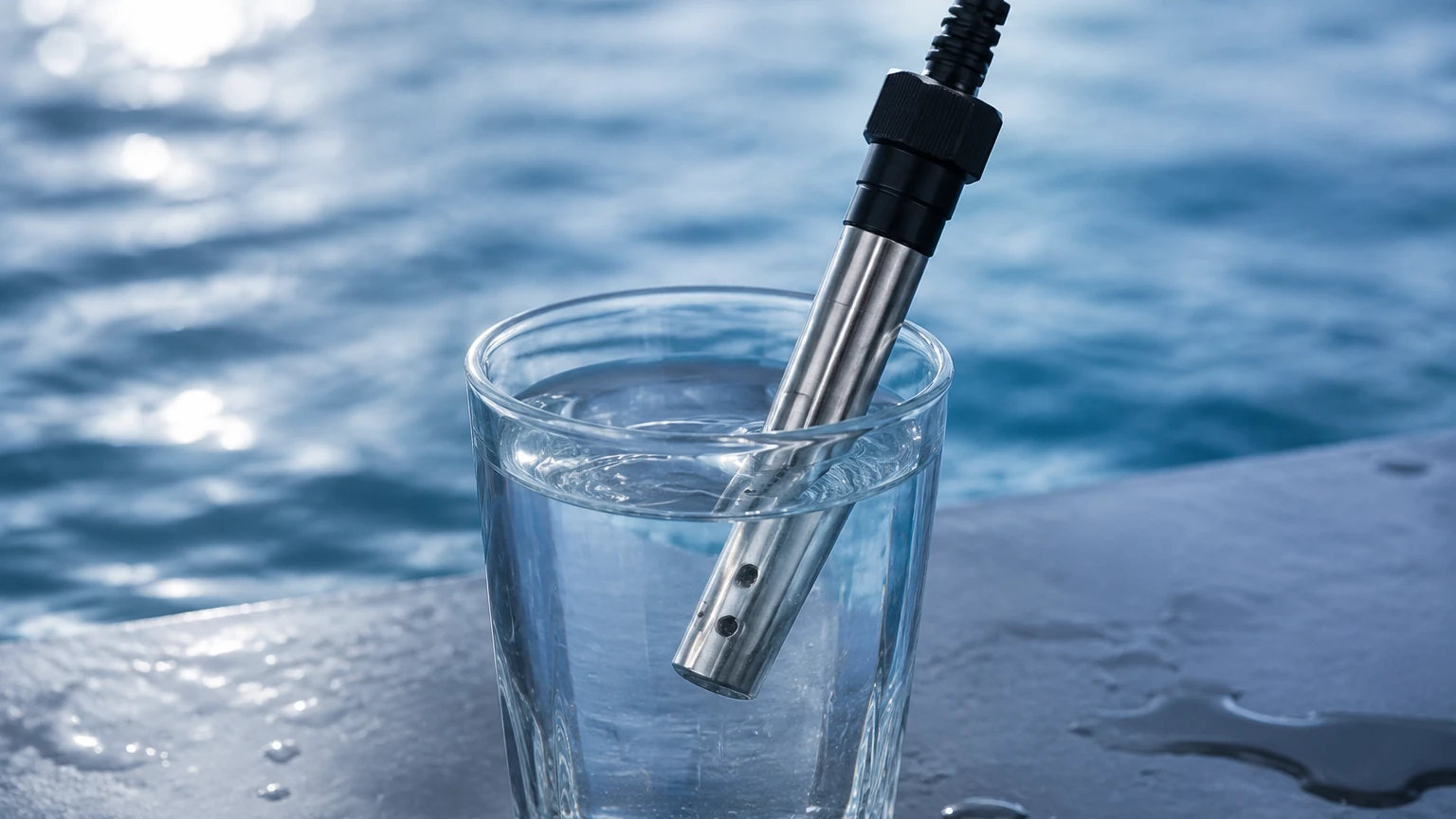
Proper installation is paramount to ensuring the longevity and accuracy of a waters conductivity detector. Incorrect placement can lead to air entrapment or sediment buildup, both of which distort readings.
Positioning and Orientation
* Full Pipe Requirement: Sensors must be installed in a location where the pipe or vessel is always full of liquid. In horizontal pipes, the sensor should be mounted on the side (3 o'clock or 9 o'clock position) to avoid air bubbles at the top and sediment at the bottom.
* Flow Direction: For contacting sensors, the liquid should flow across the electrodes to prevent the stagnation of ions and minimize fouling.
* Submersion Depth: For tank installations, the sensor must be submerged deep enough to avoid surface turbulence but high enough to avoid sludge at the bottom of the tank.
Interference and Grounding
Electrical noise from large motors or variable frequency drives (VFDs) can interfere with the low-voltage signals of a conductivity detector. Using shielded cables and ensuring the transmitter is properly grounded to the process piping is essential. In plastic piping systems, a grounding ring may be necessary to provide a stable reference point.
Limitations and Maintenance Challenges
While robust, waters conductivity detectors are not universal solutions. Engineers must account for the following limitations:
1. Non-Conductive Liquids: Conductivity sensors cannot detect hydrocarbons, oils, or highly pure solvents (unless specialized ultrapure sensors are used). For these media, radar or capacitive level sensors are required.
2. Fouling and Scaling: In contacting sensors, the buildup of calcium carbonate (scale) or biological growth on the electrodes acts as an insulator, leading to falsely low conductivity readings. Regular cleaning with a mild acid or surfactant is necessary.
3. Polarization: At high conductivities, a layer of ions can build up near the electrodes of a 2-pole sensor, creating a "polarization resistance" that errors the measurement. This is mitigated by using 4-pole or inductive sensors.
4. Air Bubbles: Air is an insulator. If air bubbles are trapped within the sensor cell or the toroidal hole, the measured conductivity will be significantly lower than the actual value.
Frequently Asked Questions (FAQ)
Q: How often should a waters conductivity detector be calibrated?
A: Calibration frequency depends on the process aggressiveness and accuracy requirements. In clean water applications, every six months may suffice. In fouling environments, monthly verification against a standard solution is recommended.
Q: Can I use a conductivity sensor to measure the concentration of a specific chemical?
A: Only if the solution is binary (e.g., NaOH and water). Since conductivity measures the total ion concentration, it cannot distinguish between different types of ions in a complex mixture.
Q: What is the maximum cable length for a conductivity sensor?
A: For contacting sensors, cable length is usually limited to 15-30 meters because cable capacitance and resistance can interfere with the signal. Inductive sensors and those with integrated pre-amplifiers can support longer distances.
Q: Why is my conductivity reading drifting?
A: Drifting is commonly caused by temperature fluctuations (if compensation is not working), electrode fouling, or the gradual depletion of the electrode material in corrosive environments.
Conclusion
The implementation of a waters conductivity detector is a strategic decision that impacts both process efficiency and equipment safety. By understanding the relationship between cell constants, temperature effects, and the physical properties of the water being measured, engineers can select a system that provides reliable data over a long service life. Whether used for monitoring water quality or as a robust point-level switch, these instruments remain a cornerstone of modern industrial liquid management. For those designing complex systems, integrating these sensors with other technologies such as radar or ultrasonic level meters ensures a redundant and highly accurate control loop.