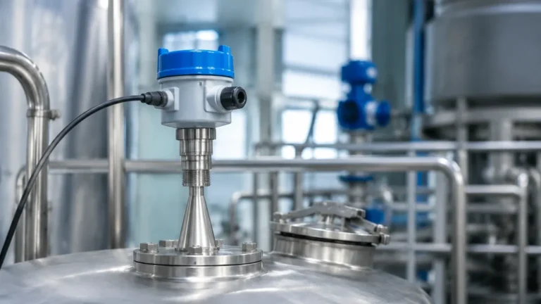
Types of Guided Wave Radar Level Transmitter
Types of Guided Wave Radar Level Transmitter: A Comprehensive Engineering Guide
In the landscape of industrial process control, accurate level measurement is a fundamental requirement for safety, efficiency, and inventory management. Among the various technologies available, Radar Level Meters have emerged as a leading choice due to their reliability in challenging environments. Specifically, Guided Wave Radar (GWR) technology offers a contact-based approach that excels where non-contact methods might struggle.
Understanding the various types of guided wave radar level transmitter is essential for instrumentation engineers and procurement specialists. This guide explores the underlying principles, probe configurations, selection criteria, and installation best practices for GWR systems in B2B industrial applications.
Measurement Principle: Time Domain Reflectometry (TDR)
Before selecting a specific probe configuration, it is vital to understand how Guided Wave Radar functions. GWR is based on the principle of Time Domain Reflectometry (TDR).
1. Pulse Emission: The transmitter electronics generate a low-energy, high-frequency electromagnetic pulse (typically in the gigahertz range).
2. Guidance: Unlike non-contact radar, which broadcasts waves through the air, GWR guides this pulse along a physical probe (a rod, cable, or coaxial tube).
3. Reflection: When the pulse reaches the surface of the medium being measured, a portion of the pulse energy is reflected back toward the transmitter. This reflection occurs because of a change in the dielectric constant ($ε_r$) between the upper medium (usually air or gas) and the process medium.
4. Calculation: The transmitter measures the time of flight—the time taken for the pulse to travel down and return. Since the speed of light is constant, the distance to the product surface is calculated as:
*Distance = (Speed of Light × Time of Flight) / 2*
Because the pulse is concentrated along a probe, the signal is less susceptible to attenuation caused by steam, foam, dust, or turbulent surfaces compared to open-air radar systems.
The Importance of the Dielectric Constant ($ε_r$)
The dielectric constant is the most critical factor in GWR performance. It determines how much energy is reflected back to the sensor.
* High Dielectric Media (ε_r > 10): Materials like water or aqueous solutions provide strong reflections, making them easy to measure with almost any probe type.
* Low Dielectric Media (ε_r < 3): Hydrocarbons, oils, and certain solids reflect very little energy. In these cases, more sensitive probe configurations, such as coaxial probes, are required to concentrate the electromagnetic field.
Primary Types of Guided Wave Radar Level Transmitter
The physical design of the probe defines the "type" of GWR transmitter. Each configuration is engineered to handle specific process conditions, tank geometries, and material properties.
1. Single Rod or Single Cable Probes
Single-element probes are the most common type used in industrial automation. They consist of a single stainless steel rod (rigid) or a weighted cable (flexible).
* Application: Best suited for liquids with high dielectric constants or for solids (in the case of reinforced cables). They are highly resistant to buildup because there is only one surface where material can cling.
* Advantages: Low maintenance, easy to clean, and cost-effective. Flexible cable versions can reach lengths of up to 30 meters (approx. 98 ft) or more.
* Limitations: They require a larger "clearance" from tank walls and internal obstructions (like ladders or agitators) because the electromagnetic field extends significantly around the probe.
2. Twin Rod or Twin Cable Probes
This type utilizes two parallel rods or cables. The electromagnetic pulse travels between the two conductors.
* Application: Used for liquids with moderate to low dielectric constants where a single rod might not provide a sufficient signal-to-noise ratio. They are often used in smaller tanks where wall interference is a concern for single-rod types.
* Advantages: The measurement field is more concentrated between the two elements, providing a stronger reflection than a single rod.
* Limitations: They are highly susceptible to "bridging." If a viscous material or a solid particle gets stuck between the two rods, the transmitter will report a false high level at that point.
3. Coaxial Probes
Coaxial probes consist of a central rod inside an outer perforated tube. This design is analogous to a coaxial cable used in electronics.
* Application: The gold standard for low-dielectric liquids (like liquid nitrogen or light hydrocarbons) and highly turbulent surfaces. It is also ideal for tanks with complex internal structures.
* Advantages: The electromagnetic field is entirely contained within the outer tube. This makes the measurement completely immune to tank walls, nozzles, or internal obstructions. It also offers the highest signal sensitivity.
* Limitations: Only suitable for clean, low-viscosity liquids. Any coating or particulate matter that enters the tube can cause measurement errors and is extremely difficult to clean.
Technical Selection Table
| Feature | Single Rod/Cable | Twin Rod/Cable | Coaxial Probe |
| :— | :— | :— | :— |
| Minimum Dielectric (ε_r) | > 10 (Direct) | > 2.0 | > 1.4 |
| Viscosity Tolerance | Excellent | Moderate | Poor |
| Resistance to Coating | High | Low | Very Low |
| Tank Wall Interference | Sensitive | Moderate | Immune |
| Max Measurement Range | Up to 60m (Cable) | Up to 20m | Up to 6m |
| Common Industry | Water, Wastewater | Chemical, Oil | LPG, Solvents |

Engineering and Installation Considerations
To ensure the longevity and accuracy of Radar Level Meters, engineers must adhere to specific installation constraints.
1. Nozzle Geometry
The nozzle is the entry point for the probe into the tank. For single-rod probes, the nozzle diameter and height can affect the signal. If the nozzle is too narrow or too long, it may create a "ringing" effect that masks the true level at the top of the tank. Generally, a nozzle diameter of 50mm to 100mm (2" to 4") is preferred.
2. The Blocking Distance (Dead Zone)
All GWR transmitters have an upper and lower "dead zone" where measurement is either impossible or inaccurate.
* Upper Dead Zone: Typically 100mm to 300mm (4" to 12"), depending on the dielectric constant and probe type.
* Lower Dead Zone: Usually 50mm to 100mm (2" to 4") from the end of the probe or the weight.
Engineers must ensure that the maximum expected liquid level does not enter the upper dead zone to avoid signal loss.
3. Internal Obstructions
For single and twin probes, a minimum distance from the tank wall and internal pipes must be maintained. A common rule of thumb is to keep the probe at least 300mm (12") away from any metal surface other than the mounting flange. If this is not possible, a coaxial probe or a bypass chamber (bridle) should be used.
4. Material Compatibility
Standard probes are typically 316L stainless steel. However, for corrosive applications involving acids or chlorides, probes may need to be coated in PTFE or PFA, or constructed from exotic alloys like Hastelloy C-276.
Limitations and Application Risks
While GWR is robust, it is not a universal solution. Buyers should be aware of the following risks:
* Heavy Coating and Bridging: In applications like wastewater treatment or thick chemical slurries, material can build up on the probe. While single rods handle this better than others, extreme buildup can still attenuate the signal or cause a "virtual" level reflection.
* Interface Measurement Complexity: GWR is excellent for measuring the interface between two liquids (e.g., oil over water). However, this requires the upper liquid to be non-conductive (low ε_r) and the lower liquid to be conductive (high ε_r). If the layers mix or form an emulsion, the interface signal may become lost.
* Mechanical Stress: In tall silos containing heavy solids (like grain or cement), the pull-down forces on a cable probe can be immense, potentially damaging the tank roof or the transmitter sensor head. Load cells or reinforced cables are often required.
Frequently Asked Questions (FAQ)
Q: Can GWR measure vacuum or high-pressure tanks?
A: Yes. Since GWR does not rely on air density or sound waves, it is unaffected by vacuum or high pressure. Welk offers specialized high-pressure seals (using ceramics or glass-to-metal seals) capable of handling pressures up to 400 bar (5800 psi).
Q: How does foam affect the measurement?
A: It depends on the foam's density and dielectric properties. Dry, light foam is usually transparent to the radar pulse. Dense, wet foam may reflect the signal, causing the transmitter to read the top of the foam layer rather than the liquid. Coaxial probes are generally the best defense against foam interference.
Q: Is it possible to shorten a GWR probe in the field?
A: Most rod and cable probes can be cut to length in the field. However, the transmitter electronics must be reconfigured with the new probe length to maintain accuracy. Coaxial probes are more difficult to modify and should usually be ordered to the exact required length.
Q: Does the tank material matter?
A: For coaxial probes, no. For single and twin probes, a metal tank acts as a ground plane, which helps the signal. If installing in a plastic or fiberglass tank, a special mounting flange or a large metal plate must be used to provide a reference ground.
Conclusion for International Buyers
Selecting the correct types of guided wave radar level transmitter requires a balance between the physical properties of the medium and the mechanical constraints of the installation site. For clean liquids and low-dielectric fuels, the coaxial probe offers unmatched precision. For general-purpose water treatment or large-scale solids storage, single rod or cable probes provide the necessary durability and ease of maintenance.
When sourcing industrial instrumentation, it is critical to confirm the dielectric constant of your medium, the presence of agitators, and the temperature/pressure requirements. By choosing the right GWR configuration, process industries can achieve high-precision level monitoring with minimal long-term maintenance costs. For more information on specific models and customized OEM/ODM services, professionals should consult technical specifications for modern Radar Level Meters to ensure the selected hardware meets the specific demands of their industrial environment.
Download Types of Guided Wave Radar Level Transmitter as a PDF